Milling is one of the most versatile machining processes used in modern manufacturing, but “milling” does not describe a single cutting method. The way a cutter approaches the workpiece, which part of the tool performs the cutting, how much of the cutter is engaged, and how the workpiece is positioned can completely change the behavior of the operation.
A large face mill removing material from a steel fixture plate operates very differently from a small end mill finishing a deep aluminum pocket. Both are milling operations, but the cutting forces, chip evacuation, achievable geometry, tool deflection, surface finish, and productivity can be very different.
Understanding the different types of milling operations therefore helps with more than terminology. It allows designers, machinists, and manufacturing engineers to choose a process that matches the geometry of the part, the required tolerance, the material, and the available machine capability.
This guide explains 11 common milling operations, how each method works, where it is typically used, and what practical differences matter when producing precision CNC machined parts.
What Is a Milling Operation?
A milling operation removes material using a rotating cutting tool while the workpiece, tool, or both move along controlled axes. Unlike turning, where the workpiece rotates continuously against a stationary cutting tool, milling normally uses an interrupted cutting action. Each tooth enters the material, forms a chip, and exits before the next cutting edge engages.
That interrupted engagement makes milling extremely flexible, but it also makes cutting behavior sensitive to tool geometry, cutter engagement, spindle speed, feed rate, workholding, and part rigidity. A cutter that runs smoothly on an open surface may behave very differently when it enters a corner or becomes surrounded by material inside a slot.
Modern CNC machining centers can perform many different milling operations without changing machines. The distinction usually comes from the cutter, toolpath, orientation, and type of feature being produced.
1. Face Milling
Face milling is used primarily to produce flat surfaces. The cutting tool is mounted with its axis approximately perpendicular to the surface being machined, and most of the cutting occurs through inserts or cutting edges positioned around the face and perimeter of the cutter.
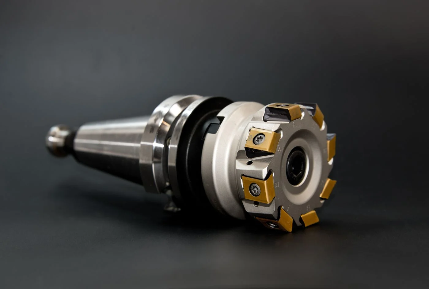
A common example is machining the top surface of an aluminum tooling plate before producing holes, pockets, and other features. The face-milled surface can establish the first reliable datum for subsequent machining. Large steel fixture plates, machine bases, mold plates, and structural components are also frequently face milled to create a flat reference surface.
Face mills usually have a significantly larger diameter than standard end mills. This allows them to cover a wide area with fewer passes, which can improve productivity and surface consistency on large flat surfaces. A 50 mm or 63 mm face mill, for example, can machine a plate much more efficiently than a 10 mm end mill traveling back and forth across the same area.
The operation is particularly effective when the workpiece and fixture are rigid. Thin plates behave differently because the downward cutting load and clamping forces can distort the material. In those cases, lighter passes or alternative workholding may be necessary to avoid machining a flat surface while the part is stressed, only to have it distort when released.
Typical applications of face milling
Face milling is commonly used for:
- fixture plates;
- mold bases;
- machine components;
- large mounting surfaces;
- housing reference faces;
- steel and aluminum plates;
- preparation of raw stock before precision machining.
Face milling is normally selected when the primary objective is flatness, surface preparation, or efficient material removal from a broad surface.
2. End Milling
End milling is probably the most versatile milling operation used in CNC machining. An end mill can cut with both its peripheral edges and, depending on the tool design, its end face. This allows a single cutter to produce pockets, contours, shoulders, slots, steps, and many other features.
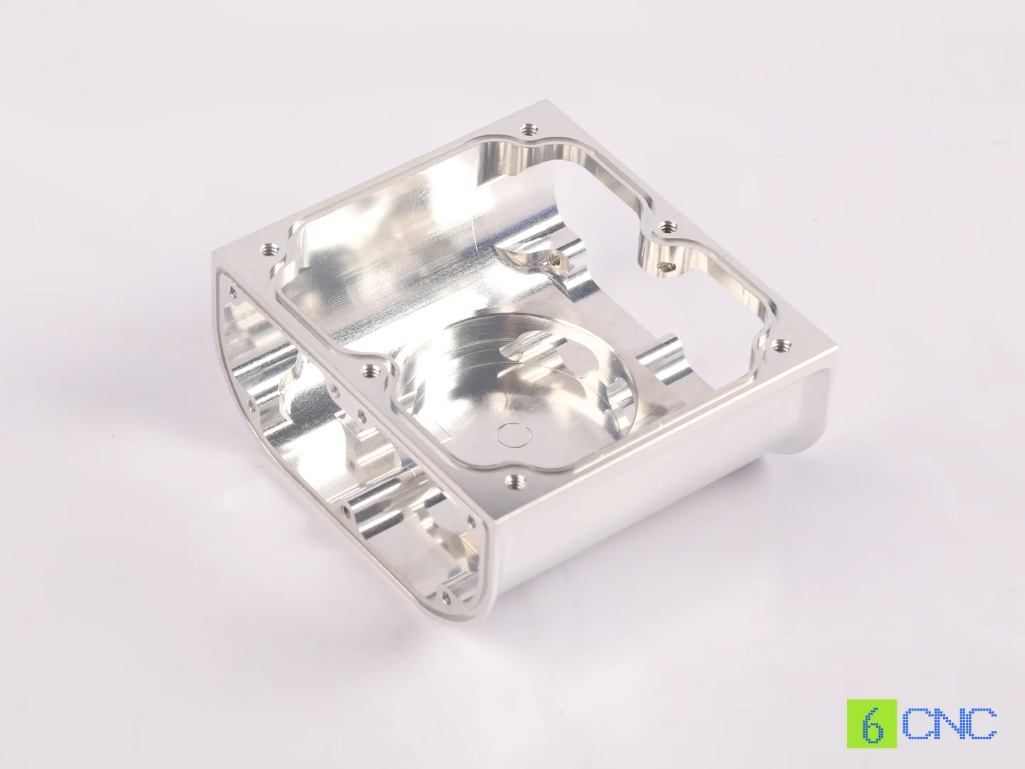
Consider an aluminum electronics enclosure. A machinist might use an end mill to rough the internal cavity, finish the outside profile, machine connector openings, and produce internal shoulders. The same general tool type can perform several different operations simply by changing the toolpath and engagement.
Tool length has a major influence on end milling performance. A short carbide end mill machining a shallow pocket is relatively rigid and can often operate at high feed rates. If the same diameter tool must extend deeply into a housing, the greater overhang increases the possibility of vibration and deflection.
This becomes particularly important when machining stainless steel, titanium, or other materials that generate higher cutting forces. The cutter may still reach the geometry, but excessive overhang can cause wall taper, chatter marks, poor dimensional accuracy, or premature tool wear.
For this reason, experienced machinists often use the shortest possible end mill for each section of the part rather than selecting one long cutter capable of reaching every feature.
3. Slot Milling
Slot milling creates narrow channels, grooves, and slots by moving the cutter through material while a large portion of the tool diameter remains engaged.
Common examples include keyways, locating slots, guide channels, T-slot preparation, and clearance grooves in machine components.
Although slot milling appears simple, it can create demanding cutting conditions. When an end mill cuts a slot equal to its own diameter, both sides of the cutter remain engaged simultaneously. Chips also have less room to escape compared with open-side milling.
This increases cutting load and heat.
Imagine a 6 mm end mill cutting a 20 mm deep slot in aluminum. At shallow depth, the operation may run smoothly. As the slot deepens, chips can remain inside the channel and be recut by the tool. Aluminum chips may then begin welding to the cutting edge, increasing load and damaging the slot walls.
In stainless steel, the problem may be different. Heat accumulation and increased cutting resistance can accelerate tool wear or cause the tool to deflect.
Deep slots are therefore often machined through multiple axial passes rather than one aggressive cut. Chip evacuation, coolant delivery, cutter flute geometry, and tool rigidity all become increasingly important as the slot becomes deeper and narrower.
4. Side Milling
Side milling uses the peripheral cutting edges of a cutter to machine vertical walls, shoulders, and side surfaces. The cutter axis is generally parallel to the surface being produced.
The process is common when finishing the outside wall of a housing, machining a shoulder on a bracket, or producing accurate parallel side surfaces.
One of the main challenges in side milling is tool deflection. When cutting forces act laterally against the tool, the cutter can bend slightly away from the workpiece. Even a rigid carbide tool will deflect under sufficient load.
This is particularly noticeable when machining tall walls.
Suppose a robotic housing contains a 40 mm tall aluminum wall with relatively little material behind it. During a heavy roughing pass, both the tool and wall may deflect slightly. Once the cutter leaves the surface, the wall springs back. The final wall may therefore show taper even if the CNC machine followed the programmed coordinates perfectly.
A common solution is to separate roughing and finishing. Most material is removed using stronger roughing passes, while a small amount of stock remains on the wall. A later finishing pass uses lighter radial engagement, reducing cutting force and improving dimensional consistency.
Side milling therefore becomes increasingly important in precision housings, brackets, frames, and thin-wall parts where wall geometry matters.
5. Plain Milling
Plain milling, sometimes called slab milling, uses the peripheral teeth of a cylindrical cutter to machine broad flat surfaces. It is traditionally associated with horizontal milling machines, where the cutter is mounted on an arbor parallel to the surface being machined.
The process is particularly effective for removing material from long, wide surfaces. Large cutters provide strong material removal capability, while horizontal machine construction can offer excellent rigidity under heavy cutting loads.
Plain milling is less common in general-purpose modern CNC shops than end milling or face milling, but it still has important uses in production environments. Heavy structural components, transmission housings, machine bases, and large steel parts may benefit from the stability and high material-removal capability of horizontal milling.
The method is especially suitable when the geometry is relatively simple but large amounts of material need to be removed efficiently.
Its limitation is flexibility. A slab cutter is excellent at producing large planar surfaces but cannot access complex pockets and contours as easily as an end mill. This is why modern machining centers often use face milling or end milling for jobs that historically would have been assigned to plain milling.
6. Profile Milling
Profile milling follows the external or internal contour of a component. Instead of simply machining a straight wall or flat face, the tool moves along a defined curved or complex path.
Typical applications include mold surfaces, aerospace structures, curved brackets, turbine components, dies, and complex product housings.
Profile milling becomes particularly interesting when the geometry changes continuously. Tool engagement can increase dramatically when the cutter enters a tight internal radius, even if the programmed feed rate remains unchanged. That sudden increase in engagement raises cutting forces and can cause visible marks, chatter, or tool deflection.
For example, consider finishing the curved outer contour of an aluminum aerospace bracket. Along the straight sections, the cutter may contact only a small portion of its diameter. When the tool enters a tight concave corner, radial engagement increases. If the machine maintains exactly the same feed rate, the cutter suddenly experiences a much heavier load.
Modern CAM systems often compensate for this using smoother toolpaths, arc transitions, or dynamic feed adjustments.
Profile milling can also use ball nose end mills when producing 3D surfaces. These tools are common in mold machining and complex aerospace parts, but they introduce another issue: cutting speed decreases toward the center of the ball nose. This means tool orientation and stepover can strongly influence both surface finish and machining time.
7. Pocket Milling
Pocket milling removes material from an enclosed area to create cavities, recesses, and internal spaces. It is one of the most common operations in CNC milling because so many machined components contain internal pockets.
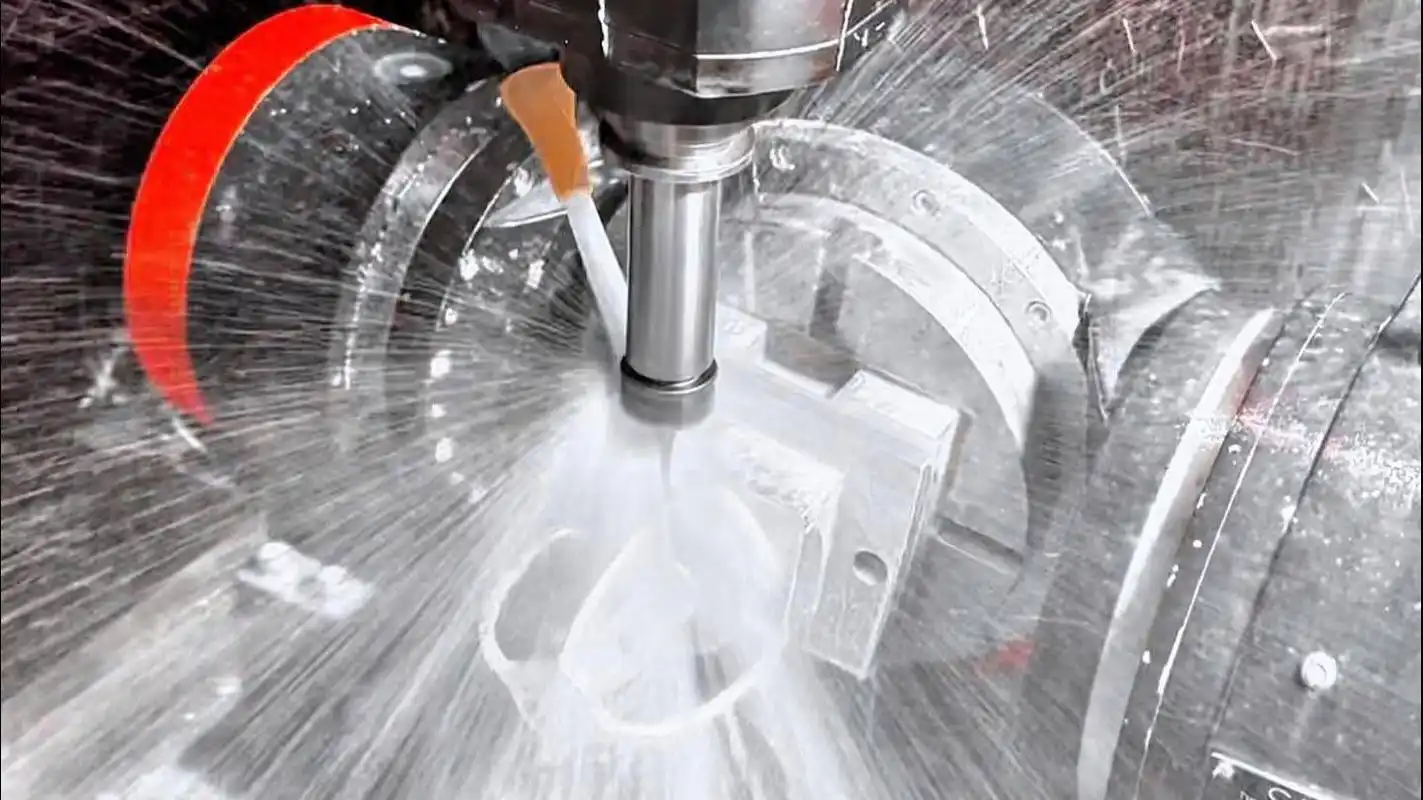
Examples include:
- electronics housings;
- hydraulic manifolds;
- aerospace brackets;
- optical equipment bodies;
- robotic components;
- mold cavities;
- machine fixtures.
A shallow open pocket may be straightforward. A deep enclosed cavity can be far more difficult.
As the cutter moves deeper into the workpiece, tool overhang normally increases and chip evacuation becomes more difficult. Chips may remain in the cavity and be cut repeatedly, which damages the surface and increases tool load.
Different materials create different problems. In aluminum, chip recutting and built-up edge are common concerns. In stainless steel and titanium, heat concentration and tool wear may become more limiting.
Modern adaptive or dynamic roughing strategies are often used for deep pocket machining. Instead of burying a large percentage of the cutter in the material, these strategies maintain relatively low radial engagement while using greater axial depth and higher feed rates.
The result can be more stable cutting forces, better chip evacuation, and longer tool life.
For particularly deep pockets, multiple tool lengths may also be used. A short tool removes material near the top of the cavity, while longer tools are introduced only after the upper material has already been cleared.
8. Thread Milling
Thread milling produces internal or external threads using a rotating cutter that follows a helical toolpath. Unlike tapping, the cutter does not have the same diameter as the finished thread. Instead, a smaller tool interpolates around the circumference of the thread.
This provides several advantages, particularly for larger or more valuable components.
Suppose a precision stainless steel housing requires an M30 internal thread near the end of a long machining cycle. Using a tap introduces a specific risk: if the tap breaks inside the finished part, removing it may be extremely difficult and the entire component can become scrap.
A thread mill reduces this risk because the tool diameter is smaller than the thread. If the cutter breaks, it is usually easier to remove from the hole.
Thread milling also provides greater control over thread size. The machinist can adjust toolpath compensation slightly to modify the effective thread diameter without changing the cutting tool.
Another benefit is flexibility. A single thread mill may sometimes produce multiple thread diameters with the same pitch, depending on tool design.
However, thread milling is generally slower than tapping for simple high-volume threaded holes. If a manufacturer needs thousands of identical M6 threads in easy-to-machine aluminum, rigid tapping may be more economical.
Thread milling becomes more attractive for larger threads, harder materials, expensive components, or applications where thread diameter control is important.
9. Helical Milling
Helical milling moves the cutter in a circular path while simultaneously feeding along the tool axis. This creates a helical trajectory that gradually enters or enlarges a hole.
One common use is creating large holes with an end mill rather than using a dedicated drill.
For example, if a component requires a 35 mm hole but the available machine setup does not include a suitable 35 mm drill, a smaller end mill can interpolate around the hole using a helical path. This also allows one cutter to produce several different hole diameters.
Helical milling creates a more gradual cutting load than direct plunging because the cutter does not engage its full diameter at once. This can be useful in harder materials or when the machine spindle does not provide ideal axial thrust for large drilling operations.
The process is also commonly used as an entry strategy for pocket milling. Instead of plunging directly into solid material, the end mill spirals downward until it reaches the required depth.
However, the final hole accuracy depends on tool deflection, machine interpolation accuracy, and cutting parameters. For precision bores, helical milling may be followed by boring, reaming, or another finishing operation.
10. Straddle Milling
Straddle milling uses two side milling cutters mounted on the same arbor to machine two parallel surfaces simultaneously. The workpiece passes between the cutters, allowing both sides to be produced in one operation.
This method is especially useful when the distance between two parallel surfaces needs to remain consistent.
For example, a component may contain two parallel mounting faces separated by a controlled width. Machining each surface independently requires two operations and introduces the possibility of setup variation. Straddle milling produces both faces under the same cutter alignment and fixture condition.
Typical applications include:
- parallel rails;
- spacer components;
- machine brackets;
- hexagonal or square features;
- repeated production components.
The process can provide high productivity, but it depends heavily on arbor rigidity and cutter spacing. The cutters must be accurately positioned relative to one another, and the machine must withstand the combined cutting forces from both sides.
Because modern CNC machining centers can produce parallel surfaces easily through repositioning, straddle milling is less common in general prototype work. It remains valuable in certain repetitive production applications where machining both surfaces simultaneously reduces cycle time.
11. Gang Milling
Gang milling uses multiple cutters mounted together on the same arbor so that several features can be machined during a single pass.
Imagine a shaft-like component that requires several grooves and shoulders at fixed distances from one another. Instead of machining one groove, repositioning the cutter, machining the next groove, and repeating the process, a gang milling setup can machine several features simultaneously.
This approach was especially important in traditional mass production before modern CNC automatic tool changers became widespread. It can still be highly efficient for repetitive components where the geometry remains unchanged over a large production run.
The advantage is cycle-time reduction. Several cutting operations happen together, potentially replacing multiple separate passes.
The disadvantage is reduced flexibility. Cutter spacing must match the component geometry exactly. If the part design changes, the tooling arrangement may also need to change. Spindle load increases because several cutters are engaged simultaneously, and one damaged cutter can affect the entire operation.
Gang milling is therefore best suited to stable, repetitive production rather than rapidly changing prototype or low-volume custom work.
Comparison of the 11 Main Milling Operations
The differences between milling operations become clearer when they are compared by geometry and typical application.
| Milling operation | Main purpose | Typical parts or features | Main advantage | Main challenge |
|---|---|---|---|---|
| Face milling | Produce broad flat surfaces | Fixture plates, mold bases, housing faces | Fast, consistent flat-surface machining | Thin parts may distort |
| End milling | General feature machining | Pockets, shoulders, contours, housings | Extremely versatile | Tool deflection with long overhang |
| Slot milling | Produce slots and grooves | Keyways, guide slots, channels | Accurate narrow features | High engagement and poor chip evacuation |
| Side milling | Machine vertical walls | Brackets, housings, shoulders | Good wall and shoulder control | Lateral cutting force and wall deflection |
| Plain milling | Machine large flat surfaces | Machine bases, structural parts | High material removal | Limited geometric flexibility |
| Profile milling | Machine contours and curved surfaces | Molds, aerospace parts, complex housings | Handles complex geometry | Changing cutter engagement |
| Pocket milling | Remove enclosed material | Housings, cavities, manifolds | Efficient internal material removal | Chips and tool reach in deep pockets |
| Thread milling | Create internal/external threads | Precision housings, hard materials | Thread size control and lower failure risk | Slower than tapping in many cases |
| Helical milling | Create holes or enter material gradually | Large holes, pocket entry | Flexible hole size and smoother entry | Accuracy depends on interpolation |
| Straddle milling | Machine two parallel surfaces | Rails, spacers, brackets | Two surfaces machined simultaneously | Precise cutter alignment required |
| Gang milling | Machine several features at once | Repetitive production parts | Very short production cycle | Limited flexibility |
How Milling Operations Affect Surface Finish and Accuracy
Choosing the correct milling operation changes more than productivity. It can directly affect surface quality, dimensional stability, and the amount of finishing work required.
Face milling generally performs well on broad flat surfaces because a large cutter covers the area with fewer passes. Attempting to machine the same surface with a small end mill may require many overlapping toolpaths, increasing cycle time and potentially leaving visible transition marks.
Slot milling creates almost the opposite cutting condition. Because the cutter is surrounded by material, chip evacuation is more difficult and cutting forces are relatively high. Deep slots can therefore show poorer wall finish or greater dimensional variation if tool deflection is not controlled.
Side and profile milling are particularly sensitive to tool deflection. A cutter may move slightly under load even when the machine axes are positioned accurately. This is why precision wall machining commonly separates roughing and finishing. The roughing tool removes most of the material, while a lighter finishing pass produces the final wall dimension.
Workpiece rigidity matters as well. A thin aluminum housing wall can deflect away from the tool, then spring back after machining. In this situation, simply increasing machine accuracy will not solve the problem because the movement occurs in the part itself.
Rough Milling vs Finish Milling
Most precision milling processes divide material removal into roughing and finishing stages.
Rough milling prioritizes productivity. Larger amounts of material are removed, and the tool may operate at higher engagement and cutting load. The objective is normally to leave the part close to its final geometry while preserving enough material for later finishing.
Finish milling uses smaller depths or widths of cut to establish final dimensions and surface quality. Because cutting forces are lower, the tool and workpiece generally experience less deflection.
Consider a precision aluminum housing with a ±0.02 mm wall requirement. Attempting to reach the final dimension during heavy roughing may produce variation because both the cutter and wall are under significant load. Leaving a small amount of material and performing a separate finishing pass gives the process a more stable final condition.
For very tight requirements, semi-finishing may also be added between roughing and finishing. This helps remove uneven stock before the final pass.
Climb Milling vs Conventional Milling
Another important distinction is the direction of cutter rotation relative to the feed direction.
In climb milling, the cutter tooth enters the material at maximum chip thickness and exits as the chip becomes thinner. On modern rigid CNC machines, this is generally the preferred strategy because it can produce lower rubbing, good surface finish, and efficient cutting.
In conventional milling, the tooth begins with very small chip thickness and exits with a thicker chip. The cutter tends to push differently against the workpiece, and more rubbing may occur at the beginning of engagement.
Conventional milling can still be useful under certain conditions, such as machining some cast or scaled surfaces, dealing with particular workholding conditions, or controlling cutter behavior on specific features.
Neither strategy should be selected purely from terminology. Machine backlash, fixture rigidity, material condition, cutter geometry, and surface requirements all influence the final choice.
How Material Changes the Milling Strategy
The same milling operation can behave completely differently depending on the material being machined.
Aluminum
Aluminum alloys such as 6061 and 7075 can generally be machined at relatively high cutting speeds. However, poor chip evacuation can cause aluminum chips to weld to the cutting edge, particularly in deep slots and pockets.
Large flute spaces, sharp cutting edges, and effective chip evacuation are therefore important.
Stainless steel
Stainless steel usually produces higher cutting forces and greater heat concentration than aluminum. Excessive tool rubbing can also contribute to work hardening.
Stable engagement, rigid tooling, and controlled heat become increasingly important in deep pockets and long-reach milling.
Titanium
Titanium alloys such as Ti-6Al-4V place even greater demands on cutting-tool management. Heat remains concentrated near the cutting edge, while long tool engagement can shorten tool life.
Low radial engagement, stable cutting conditions, appropriate coolant delivery, and controlled tool wear are commonly more important than simply maximizing material removal.
Engineering plastics
Materials such as POM, PEEK, PTFE, and nylon introduce different challenges. Cutting forces may be lower, but heat and clamping can cause dimensional movement. Some polymers also absorb moisture or have high thermal expansion compared with metals.
This means the most aggressive metal-cutting strategy is not automatically appropriate for plastic parts.
Which Milling Operation Should You Choose?
The best milling operation depends primarily on geometry, material, tolerance, and production requirements rather than the name of the operation.
For a large flat steel plate, face milling may be the obvious choice. A deep enclosed aluminum cavity will likely rely on pocket milling with controlled-engagement roughing. A precision stainless steel housing containing a large thread may benefit from thread milling instead of tapping.
More complex components usually combine several operations.
A robotic gearbox housing, for example, may begin with face milling to establish a datum. End milling and pocket milling then remove internal material. Side milling finishes the walls, helical milling creates larger openings, and thread milling produces selected threaded features.
The final process is therefore rarely defined by a single operation.
Manufacturing engineers normally build a sequence of milling strategies that balances tool access, rigidity, machining time, tolerance, and inspection requirements.
Milling Operations in 3-Axis and 5-Axis CNC Machining
Many of the operations described above can be performed on a standard 3-axis machining center. Face milling, pocket milling, slotting, profiling, and thread milling are all routine 3-axis operations when the required features are accessible from one orientation.
The limitation appears when the part contains features on several faces or at compound angles.
For example, an aerospace bracket may contain pockets on the top surface, angled holes on the side, and a curved feature on another orientation. A 3-axis process may require several fixtures and setups to reach those features.
A 5-axis machine can rotate the part or tool so that additional surfaces become accessible without repeatedly removing the workpiece. This can reduce datum-transfer error and allow shorter cutting tools to reach complex geometry.
Five-axis machining does not replace the individual milling operations. Instead, it changes how those operations can be oriented and combined.
A five-axis machine may still perform face milling, pocket milling, profile milling, and side milling—the difference is that the tool can approach the component from more useful directions.
Common Milling Problems and What Usually Causes Them
Even when the correct milling operation has been selected, problems can still develop if the cutter, setup, or parameters are unsuitable.
Chatter
Chatter often appears when the combination of tool overhang, cutting force, fixture rigidity, and spindle speed creates an unstable vibration condition. Long-reach end milling and deep pocket machining are common examples.
Reducing tool overhang, changing spindle speed, reducing engagement, or improving workholding may solve the problem more effectively than simply reducing feed.
Poor surface finish
Poor finish can result from worn tools, excessive runout, vibration, recutting chips, unstable engagement, or inappropriate finishing parameters.
The visible surface defect often provides clues about the underlying cause.
Wall taper
Wall taper commonly appears during side milling when the cutter deflects under lateral cutting force. Thin parts can make the problem worse because the workpiece also moves.
Separate finishing passes with lower engagement are commonly used to improve wall accuracy.
Rapid tool wear
Tool wear may result from excessive heat, unsuitable cutting speed, unstable engagement, insufficient coolant, or machining an abrasive or difficult material.
Simply replacing the tool more frequently can hide the underlying process problem without actually solving it.
Chip recutting
Chip recutting is particularly common in deep pockets and slots. Chips remain near the tool instead of leaving the cutting zone, causing the cutter to machine the same material fragments repeatedly.
This increases heat, damages the machined surface, and can cause built-up edge in aluminum.
Milling Operation Selection by Part Feature
A useful way to select an operation is to start from the feature rather than from the machine.
| Part feature | Common milling choice |
|---|---|
| Large flat reference surface | Face milling |
| General cavity | Pocket milling / end milling |
| Narrow groove | Slot milling |
| Precision vertical wall | Side milling |
| External curved contour | Profile milling |
| Large internal thread | Thread milling |
| Large interpolated hole | Helical milling |
| Broad horizontal surface on horizontal machine | Plain milling |
| Two parallel production surfaces | Straddle milling |
| Multiple repeated grooves or shoulders | Gang milling |
This is only a starting point. Tool access, depth, tolerance, quantity, and material may change the most efficient process.
How 6CNC Approaches Precision Milling
At 6CNC, selecting a milling operation is part of the overall process planning rather than simply matching a feature to a cutter. For prototype and small-batch parts, we consider how geometry, material, tolerance, tool access, workholding, and inspection interact before finalizing the machining sequence.
A complex component may combine several milling strategies with other manufacturing processes. For example, a precision housing might require 5-axis milling for multi-face features, grinding for a tightly controlled reference surface, or Wire EDM for a narrow internal feature that is difficult to produce with a rotating cutter.
Our machining capabilities include CNC milling, 5-axis machining, CNC turning, mill-turn machining, precision grinding, and supporting processes for custom precision parts. Inspection can include CMM, optical measurement equipment, gauges, micrometers, surface roughness measurement, and other dimensional verification methods according to project requirements.
For small-batch production, the objective is not simply to create one successful part. The machining method, fixture, toolpath, and inspection strategy also need to remain repeatable as production moves from the first article into the rest of the batch.
Final Thoughts
The 11 types of milling operations discussed in this guide are not simply different names for ways of removing material. Each creates a different combination of cutting force, tool engagement, chip evacuation, geometry, and surface condition.
Face milling is efficient for broad flat surfaces. End milling provides exceptional flexibility. Slot and pocket milling demand careful control of engagement and chips. Profile and side milling require attention to deflection, while thread and helical milling solve specific hole and thread-making problems. Plain, straddle, and gang milling remain valuable where production geometry favors dedicated cutter arrangements.
In real CNC manufacturing, several of these methods are often combined on the same component.
The best milling process is therefore not necessarily the fastest individual operation. It is the sequence of operations that produces the required geometry, tolerance, surface finish, and quantity with the most stable manufacturing process.
If you are developing a precision milled component, 6CNC supports custom CNC machining from prototype through small-batch production. Send your CAD files, engineering drawings, material specification, and quantity requirements for a manufacturing review and quotation.
Frequently Asked Questions
What are the most common milling operations?
Some of the most common CNC milling operations include face milling, end milling, slot milling, side milling, pocket milling, and profile milling. Thread milling and helical milling are also frequently used for threaded features and large holes.
What is the difference between face milling and end milling?
Face milling primarily uses a large cutter to machine broad flat surfaces with the cutter axis perpendicular to the workpiece. End milling is more versatile and can machine pockets, walls, slots, shoulders, and contours using the cutter’s peripheral and end cutting edges.
What is the difference between pocket milling and slot milling?
Pocket milling removes material from an enclosed area and usually allows the cutter to follow multiple internal toolpaths. Slot milling creates a relatively narrow channel, often with much greater cutter engagement. Because the cutter can be surrounded by material, slot milling typically creates more demanding chip-evacuation and cutting-load conditions.
Which milling operation is best for flat surfaces?
Face milling is generally preferred for large flat surfaces because the large cutter diameter covers more area per pass. End milling may be more appropriate for small flat areas or surfaces located inside complex geometry.
Which milling method is used for threads?
Thread milling uses a smaller rotating cutter following a helical path to create internal or external threads. It provides good thread-size control and can be particularly useful for larger threads, hard materials, or expensive components.
What is the purpose of helical milling?
Helical milling is commonly used to enter material gradually or produce holes larger than the cutting tool. The cutter moves in a circular path while simultaneously feeding along the axis, producing a helical motion.
Why are deep pockets difficult to mill?
Deep pockets require longer tool reach and make chip evacuation more difficult. Increased tool overhang reduces rigidity, while trapped chips can increase heat and damage the machined surface. Deep pockets therefore often require specialized roughing strategies and multiple tool lengths.
What milling operation is suitable for complex curved surfaces?
Profile milling is commonly used for complex contours and curved surfaces. Ball nose cutters and multi-axis machining may be used when the geometry includes 3D surfaces such as mold cavities, aerospace contours, or turbine-related components.
Can 5-axis machines perform the same milling operations as 3-axis machines?
Yes. Five-axis machines can perform many of the same operations, including face milling, pocket milling, end milling, and profile milling. The additional axes allow the tool to approach the component from more orientations, which can reduce setups and improve access to complex geometry.
How do I choose the right milling operation?
Start with the feature geometry, then consider material, depth, tool access, tolerance, surface finish, quantity, and machine capability. Complex parts often require several milling operations rather than one single method.