![Comparison of Operating Principles: This figure illustrates a microscopic comparison of the surface waviness and residual scallop height generated by a face milling cutter and a ball-nose cutter under different stepover and step-down settings. [Figure 4-1]](https://6-cnc.com/wp-content/uploads/2026/09/4151.png)
Executive Summary: Surface Roughness Baselines
- Kinematic Finish Advantages: CNC turning naturally yields superior surface finish metrics (Ra) compared to milling due to continuous single-point shearing. Standard turned shafts regularly achieve Ra 0.4–1.6 µm (16–63 µin).
- Milled Face Scallop Profiles: Surface finish in milling is heavily dependent on stepover distances and tool tip radii. Standard facing operations comfortably yield Ra 0.8–3.2 µm (32–125 µin).
- The Material Factor: Soft, ductile materials (e.g., Copper, Pure Aluminum) are prone to built-up edge (BUE), which degrades surface topography. Harder, highly machinable alloys (e.g., Aircraft Aluminum, Pre-hardened Steel) consistently yield cleaner surface finishes.
- Secondary Finishing Triggers: Specifications demanding Ra < 0.4 µm (16 µin) cannot be reliably held through direct chip-cutting operations on prototypes. Such tight parameters dictate a routing shift toward cylindrical or surface grinding processes.
1. The Tribology of Chip Cutting: How Surface Texture is Formed
In precision subtractive manufacturing, surface finish—quantified primarily by the arithmetic average roughness (Ra)—is the direct geometric signature of the toolpath left upon the workpiece. Achieving an optimal Ra value is not merely an aesthetic goal; it dictates mechanical seal performance, fatigue life, and wear resistance in dynamic assemblies.
The generation of surface texture is governed by machine tool rigidity, spindle vibration harmonics, cutting speeds, and fluid dynamics. As the cutting edge shears material away, it leaves behind microscopic peaks and valleys.
Unchecked friction, tool wear, and poor chip evacuation introduce structural surface defects such as micro-tearing and built-up edge (BUE). This article addresses how to manage these variables across turned cylinders and milled planes, ensuring compliance with international benchmarks like the ISO 21920 profile surface roughness standard.
2. Roughness Envelopes (Ra) Matched by Process and Material
Material chemistry and hardness significantly alter the achievable surface texture during cutting operations. The table below outlines realistic, repeatable Ra target ranges for prototypes and production components without secondary abrasive operations:
| Material Classification | CNC Turning Standard Ra (µm / µin) | CNC Turning Target Limit (µm / µin) | CNC Milling Standard Ra (µm / µin) | CNC Milling Target Limit (µm / µin) |
| Aluminum Alloys (6061-T6, 7075-T6) | 0.8 µm / 32 µin | 0.4 µm / 16 µin | 1.6 µm / 63 µin | 0.8 µm / 32 µin |
| Stainless Steels (304, 316L, 17-4 PH) | 1.6 µm / 63 µin | 0.8 µm / 32 µin | 2.2 µm / 87 µin | 1.2 µm / 47 µin |
| Titanium Alloys (Grade 5 / Ti-6Al-4V) | 1.6 µm / 63 µin | 0.8 µm / 32 µin | 3.2 µm / 125 µin | 1.6 µm / 63 µin |
| Carbon & Tool Steels (4140, P20) | 1.6 µm / 63 µin | 0.6 µm / 24 µin | 2.2 µm / 87 µin | 0.8 µm / 32 µin |
| Engineering Plastics (POM-C, PEEK) | 0.8 µm / 32 µin | 0.4 µm / 16 µin | 1.6 µm / 63 µin | 0.8 µm / 32 µin |
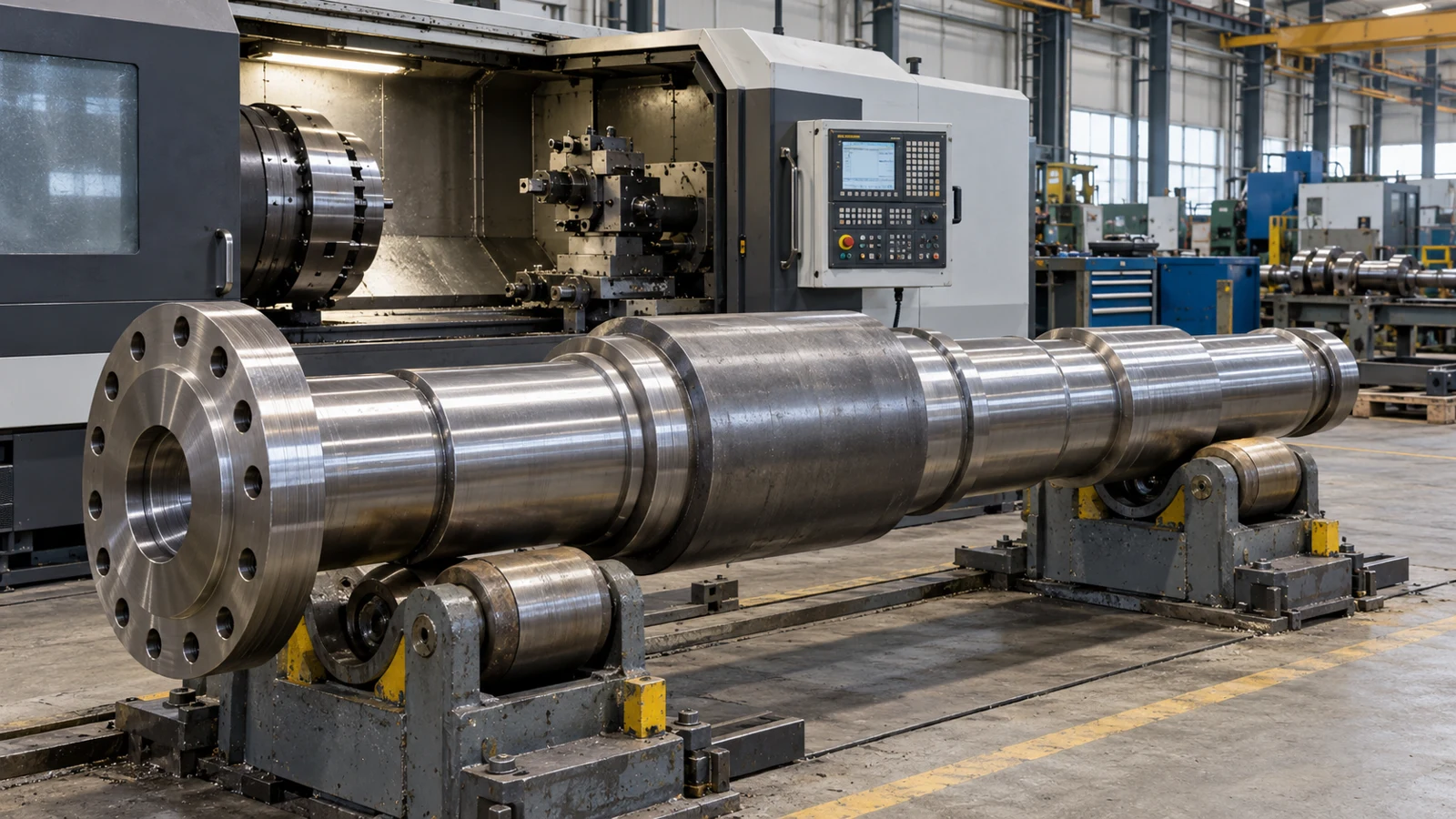
3. Turned Shafts: Continuous Shearing and Cusps
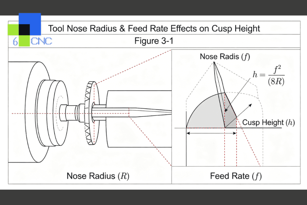
The Geometry of Turning Clefts
In single-point CNC turning, the cutting insert maintains continuous engagement with the rotating workpiece. The resulting surface profile resembles a continuous micro-screw thread. The theoretical peak-to-valley roughness (Rt) is mathematically driven by the tool tip geometry and feed rate.
Based on this structural mechanic, reducing the feed rate or increasing the tool nose radius decreases cusp height, improving the Ra value.
Material-Specific Limitations
When turning ductile alloys like Stainless Steel 304, the high thermal accumulation at the cutting zone can cause material to weld onto the tool insert tip. This results in built-up edge (BUE), which alters the tool geometry and leaves random micro-tearing marks along the shaft diameter.
To achieve a clean Ra 0.4 µm (16 µin) profile on a turned shaft, machinists must combine high cutting speeds with premium, polished carbide inserts and pressurized coolant to break chips quickly. This approach is highly effective for processing materials like Al6061-T6 and 7075 alloys.
4. Milled Faces: Stepover, Scallop Heights, and Toolpath Effects
![Comparison of Operating Principles: This figure illustrates a microscopic comparison of the surface waviness and residual scallop height generated by a face milling cutter and a ball-nose cutter under different stepover and step-down settings. [Figure 4-1]](https://6-cnc.com/wp-content/uploads/2026/09/4151-1024x680.png)
The Scallop Generation Profile
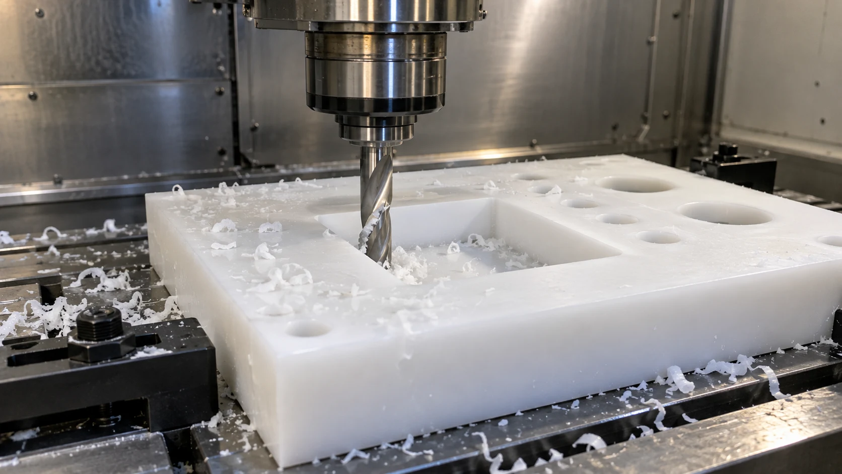
Unlike turning, CNC milling features an intermittent cutting action that generates a multi-directional surface texture. When using a flat face mill or end mill across a planar surface, two distinct roughness profiles are formed:
- Perpendicular to Tool Motion: Driven by the tool insert’s bottom edge geometry.
- Parallel to Tool Motion (Stepover Direction): Driven by the stepover distance (radial depth of cut) and the trailing edge swipe of the tool.
When utilizing ball-nose end mills for complex 3D surfacing on multi-axis CNC mills, the stepover distance creates distinct micro-ridges known as scallop heights. To maintain a flat face tolerance within Ra 0.8 µm (32 µin), the stepover must often be limited to 5% to 10% of the tool cutter diameter. This configuration substantially increases machine toolpath length and cycle runtime.
The Single-Setup Path Priority
To minimize surface variation on large planar surfaces, engineers should adhere to the Single-Setup Principle. The face mill diameter should ideally exceed the total width of the raw block. This allows the plane to be swept in a single, uninterrupted pass.
If multiple overlapping tool passes are required, slight misalignments or machine vibrations can introduce a stepped discrepancy (axial mismatch) between paths, complicating flatness tolerances and surface quality.
5. Finishing Triggers: When to Transition to Secondary Operations
Direct subtractive chip cutting hits a physical efficiency barrier when specifications call for absolute mirror finishes or sub-micron seal performance. The table below defines the clear cut-off boundaries where design requirements necessitate secondary abrasive or mechanical post-processing:
                      SURFACE ROUGHNESS FINISHING TRIGGERS
  +-----------------------------------------------------------------+
  | Standard CNC Turning/Milling  | Ra >= 0.8 µm | Direct Cutting    |
  +-----------------------------------------------------------------+
  | Precision Wiper Inserts       | Ra 0.4 µm    | Extreme Feed Limit|
  +-----------------------------------------------------------------+
  | Secondary Abrasive Grinding   | Ra 0.2 µm    | Mandated Trigger  |
  +-----------------------------------------------------------------+
Key Triggers for Secondary Post-Processing:
- Dynamic Rotary Seals (Ra 0.2–0.4 µm / 8–16 µin): Shafts operating inside high-pressure hydraulic or lip seal assemblies require a smooth, low-friction finish to prevent premature seal wear. Direct lathe turning cannot reliably hit these targets across an entire production batch without rapid tool degradation. These components should be routed to secondary cylindrical ID/OD grinding operations.
- Structural Flatness and Sealing Gaskets (Ra <= 0.4 µm / 16 µin): Vacuum chambers and fluid manifold split-faces require near-perfect coplanarity to ensure no-leak performance under deep pressure deltas. Once the requirement drops below Ra 0.4 µm (16 µin), routing must switch from conventional milling to specialized double-disk surface grinding or precision lapping.
- Hardened Component Finishing (>50 HRC): Trying to achieve clean surface profiles on hardened tool steel components through direct milling causes immediate tool chipping. Parts should be machined in an annealed state, heat-treated, and then brought to final surface specification via precision abrasive wheel setups.
6. Setup Complexity and Production Economics
Surface finish requirements are direct cost drivers in precision manufacturing. Demanding an overly polished finish where a standard machined look suffices adds considerable production overhead:
- Cycle Time Inflation: Moving a specification from Ra 3.2 µm (125 µin) to Ra 0.8 µm (32 µin) requires the machine operator to execute fine-pitch finishing passes at significantly reduced feed rates. This configuration can easily double or triple the localized machine runtime per component.
- Tool Lifecycle Cost: Achieving ultra-smooth finishes relies on maintaining pristine cutting edges. To hold a tight Ra target across an entire production batch, tool inserts must be replaced frequently before normal micro-chipping can mar the workpiece surface, driving up overall tooling overhead.
- Setup Costs for Multi-Axis Geometry: If complex features require high-quality surface finishes across multiple angled planes, the component may need to be routed to specialized multi-axis machinery. While advanced Mill-Turn systems can drop complex hybrid components complete in a single setup, their elevated hourly machine rates require careful cost analysis. Reserve these configurations for intricate geometries or larger production runs where eliminating manual secondary operations justifies the machine expense.
7. Metrology and the 6CNC Surface Verification Matrix
The precision manufacturing environment at 6CNC pairs high-precision subtractive machinery with calibrated surface topography inspection systems:
- Subtractive and Abrasive Multi-Axis Footprint: Our production floor operates high-speed vertical CNC milling arrays and bar-fed live-tool lathes alongside precision grinding operations to deliver stable, single-setup component execution.
- Tactile and Optical Profilometry: Every tight-specification component undergoes rigorous evaluation using high-precision diamond-stylus profilometers. All surface texture sweeps comply with ISO 21920 profile data extraction standards, providing certified Ra, Rz, and Rmax documentation.
- Comprehensive Quality Validation: Geometric tolerances, including flatness and true position, are confirmed via coordinate measuring machines (CMM) calibrated to strict ISO 10360 measurement guidelines.
By integrating realistic surface roughness parameters into your initial product architecture, you eliminate unnecessary processing steps and minimize unit manufacturing costs. Upload your native CAD assets and technical drawings directly to the secure processing portal for an automated engineering DFM review and quote to align your project blueprints with optimized manufacturing paths.