
Build-to-Print Opto-Mechanical Hardware
CNC Machining for Precision Optical Components
Precision-machined lens mounts, barrels, housings, stages, rings, and alignment hardware for imaging, laser, sensing, laboratory, and optical instrument assemblies.
Critical datums and optical-axis alignment
Prototype and repeat small batches
DFM, inspection, and finishing support
1–600 pcs
Prototype and repeat small-batch range
140+ Machines
Milling, turning, and multi-axis capacity
Feature-Level QC
Inspection matched to drawing requirements
Global Delivery
Support for international optics teams
Mechanical accuracy that protects optical performance
Precision CNC Machining for Optical Assemblies
Optical systems depend on the mechanical relationships between lenses, mirrors, sensors, emitters, apertures, and adjustment mechanisms. Small errors in concentricity, flatness, perpendicularity, bore position, or thread geometry can shift alignment and complicate assembly.
6CNC manufactures build-to-print metal and engineering-plastic components for cameras, microscopes, telescopes, laser systems, machine vision, metrology equipment, scientific instruments, and photonics assemblies.
Our scope is opto-mechanical hardware. Optical glass generation, lens polishing, optical coating, and interferometric certification are not standard CNC metal-machining services and must be sourced or reviewed separately.
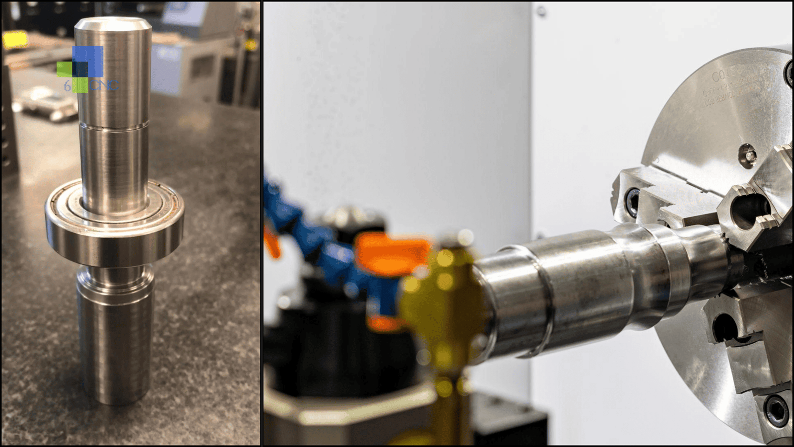
Typical opto-mechanical components
Precision Optical Components We Machine
Lens Barrels and Cells
Threaded barrels, retaining-ring seats, shoulders, precision bores, spacers, and controlled optical interfaces.
Optical Mounts and Brackets
Mirror mounts, lens holders, detector brackets, kinematic interfaces, and rigid alignment structures.
Camera and Sensor Housings
Protective enclosures with connector cutouts, heat paths, sealing features, mounting datums, and internal light control.
Adjustment Components
Focus rings, threaded adjusters, stages, carriers, retainers, adapters, and fine-positioning hardware.
Apertures and Baffles
Mechanical apertures, stops, internal baffles, blackened components, and stray-light management structures.
Instrument Frames and Bases
Stable platforms, optical benches, interface plates, reference structures, and compact instrument chassis.
Machining capabilities
CNC Processes for Precision Optics Hardware
Precision CNC Turning
Lens barrels, rings, spacers, sleeves, threaded retainers, and coaxial bore-and-shoulder relationships.
CNC Milling
Mounts, stages, housings, pockets, datum faces, sensor patterns, and instrument structures.
5-Axis Machining
Complex multi-face parts, angled optical paths, sculpted lightweight geometry, and fewer-setup alignment control.
Mill-Turn Machining
Concentric components that also require flats, cross-holes, slots, connector features, or off-axis mounting points.
Prototype Machining
Functional hardware for optical fit checks, alignment studies, thermal tests, and instrument validation.
Surface Finishing
Black anodizing, passivation, plating, conversion coating, polishing, marking, masking, and cosmetic finishes.
Stability, weight, and surface control
Materials for Opto-Mechanical Components
Material
Aluminum 6061
Typical Optical-System Use
Housings, mounts, instrument frames
Engineering Consideration
Machinability, low weight, thermal conductivity, and anodizing response
Aluminum 7075
Typical Optical-System Use
Stiff lightweight structures and loaded mounts
Engineering Consideration
Higher strength with different corrosion and finishing considerations
Stainless steel
Typical Optical-System Use
Adjusters, shafts, inserts, stable interfaces
Engineering Consideration
Strength and corrosion resistance with greater mass and lower conductivity
Titanium
Typical Optical-System Use
Low-expansion interfaces and selected precision structures
Engineering Consideration
Strength-to-weight benefits, cost, and more demanding machining
Copper alloys
Typical Optical-System Use
Thermal paths, conductive parts, and selected mechanisms
Engineering Consideration
Thermal or electrical performance balanced against mass
Engineering plastics
Typical Optical-System Use
Insulators, low-friction guides, covers, and spacers
Engineering Consideration
Thermal expansion, moisture absorption, creep, outgassing, and cleanliness
Optics note:
thermal expansion, blackening, vacuum compatibility, cleanliness, outgassing, and galvanic compatibility should be defined before material and finish selection.
Alignment and repeatability priorities
How We Protect Opto-Mechanical Accuracy
Datum Strategy
Machining and inspection reference the functional faces, bores, and axes defined by the optical assembly.
Coaxial Feature Control
Bores, shoulders, threads, seats, and cylindrical interfaces are planned to reduce setup-related alignment error.
Distortion Management
Wall thickness, stress relief, machining sequence, clamping, and finish processes are reviewed for dimensional stability.
Surface and Edge Control
Sealing faces, light-control surfaces, cosmetic zones, burrs, threads, and optical-contact areas receive defined treatment.
Inspection Planning
CMM, optical measurement, gauges, roughness testing, and dimensional reports are selected to match drawing requirements.
Revision Traceability
Approved drawings, controlled files, inspection records, and finish specifications support repeat builds.
Design for alignment
Opto-Mechanical Part DFM Checklist
- Identify the optical axis and functional datum structure
- Define critical bore, shoulder, thread, and mounting relationships
- Separate optical tolerances from noncritical dimensions
- Use practical internal radii and accessible deep features
- Account for clamping and thin-wall distortion
- Allow for anodizing, plating, or coating thickness at fits
- Specify burr, cleanliness, blackening, marking, and masking needs
- Confirm how critical features will be measured
Project workflow
From Optical CAD to Finished Hardware
1
Share Project Data
Send CAD files, drawings, material, quantity, finish, assembly function, and inspection requirements.
2
DFM and Datum Review
We review geometry, optical interfaces, tolerance relationships, tooling, inspection, cost, and lead time.
3
Machine and Inspect
Components are produced and verified against the agreed drawing and quality scope.
4
Validate and Repeat
Complete optical assembly testing, approve revisions, and release repeat batches when ready.
Inside 6CNC
Flexible Manufacturing for Optical Instrument Teams
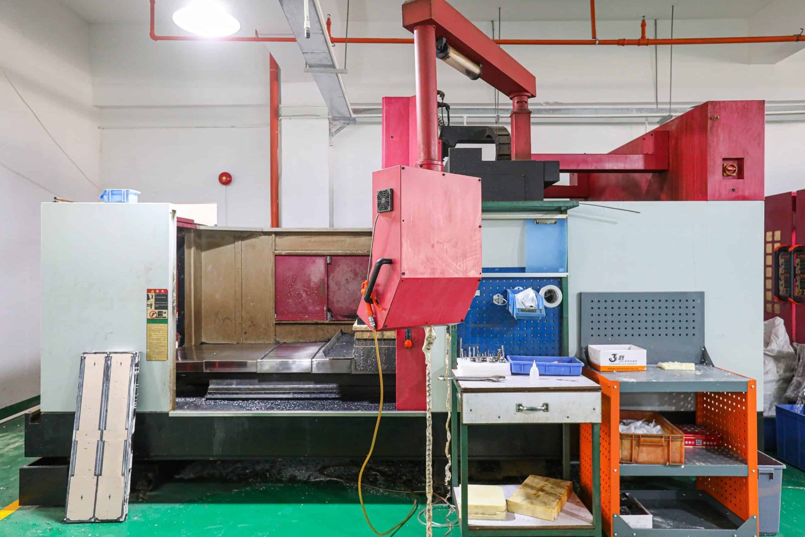
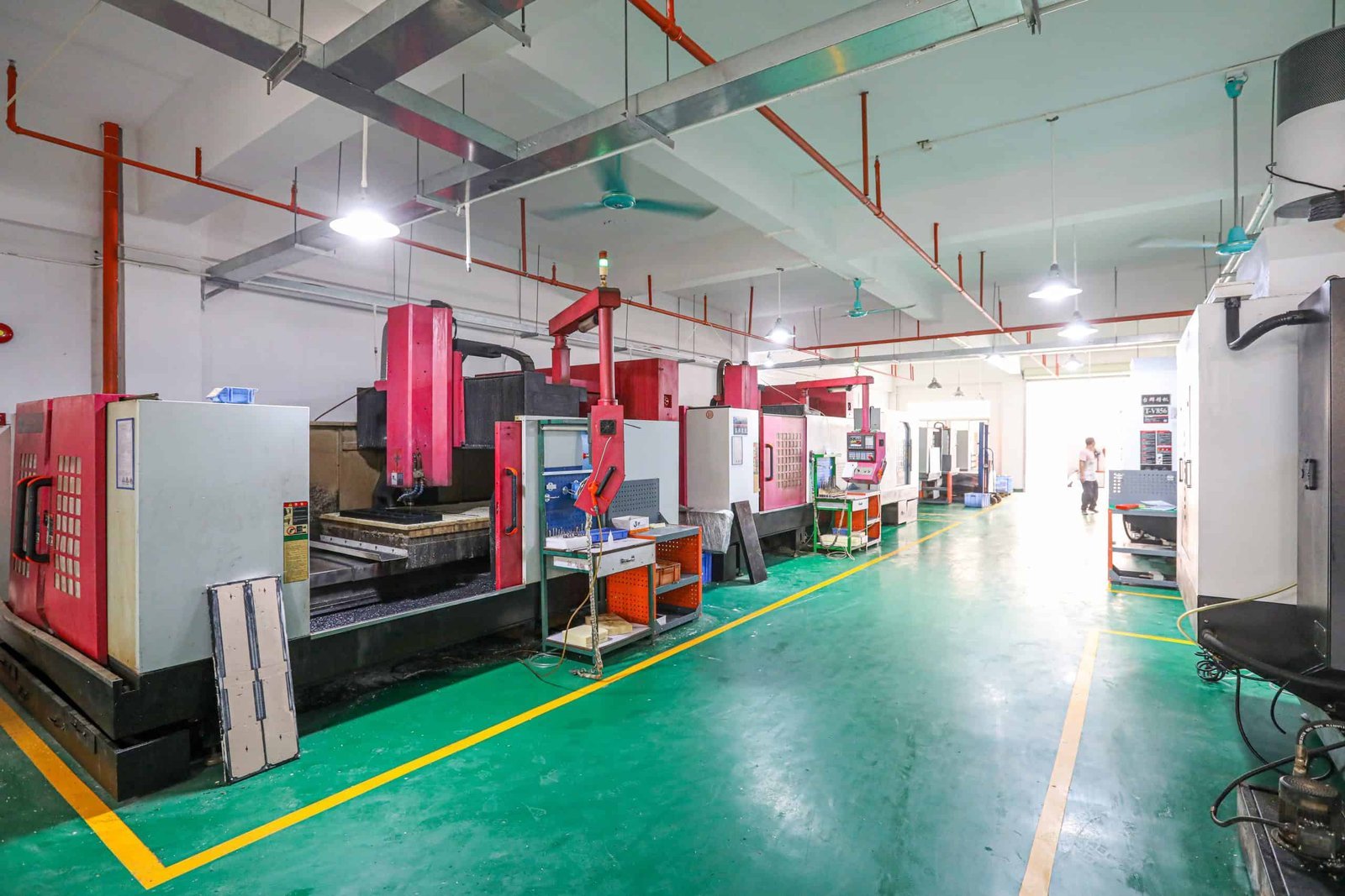
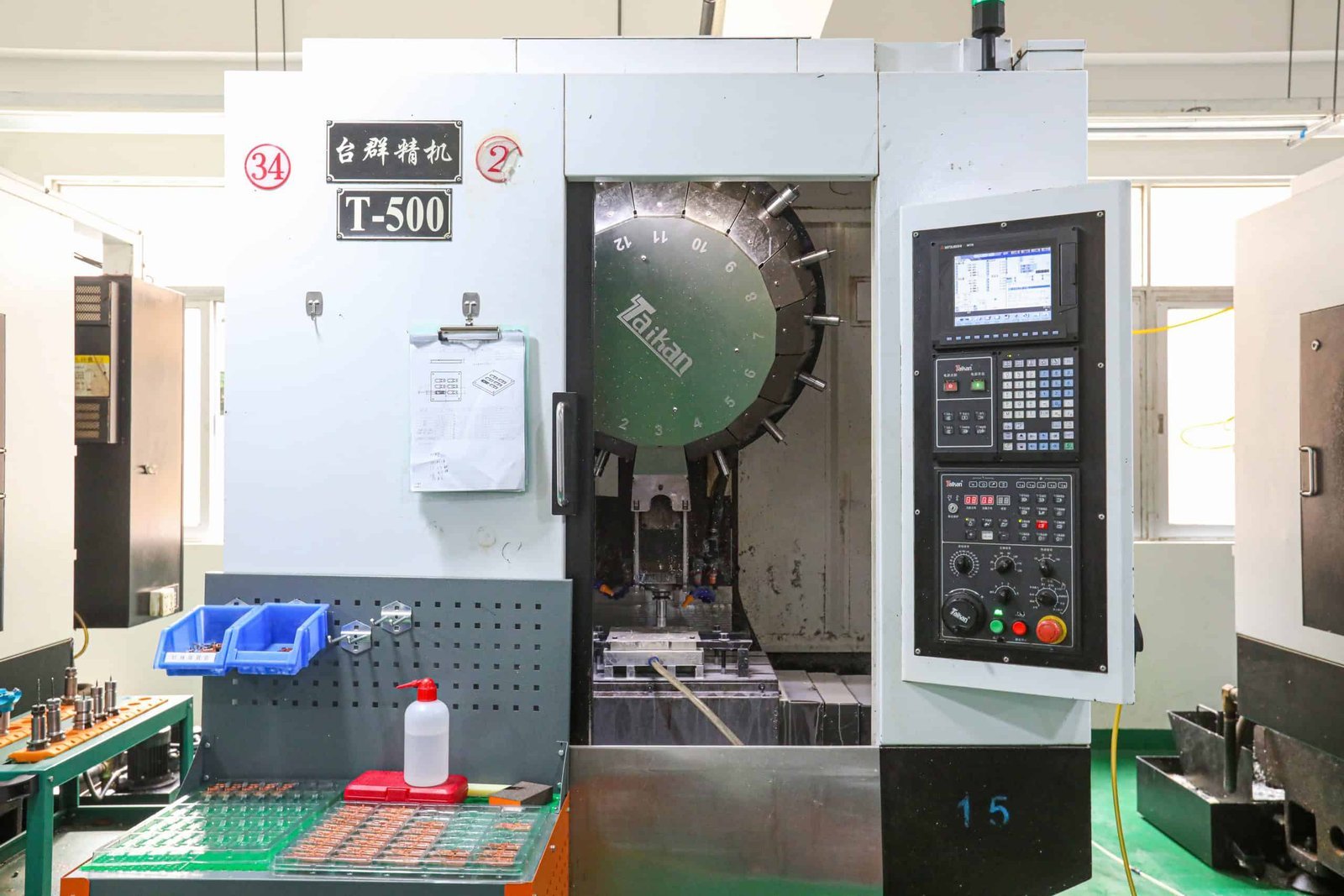
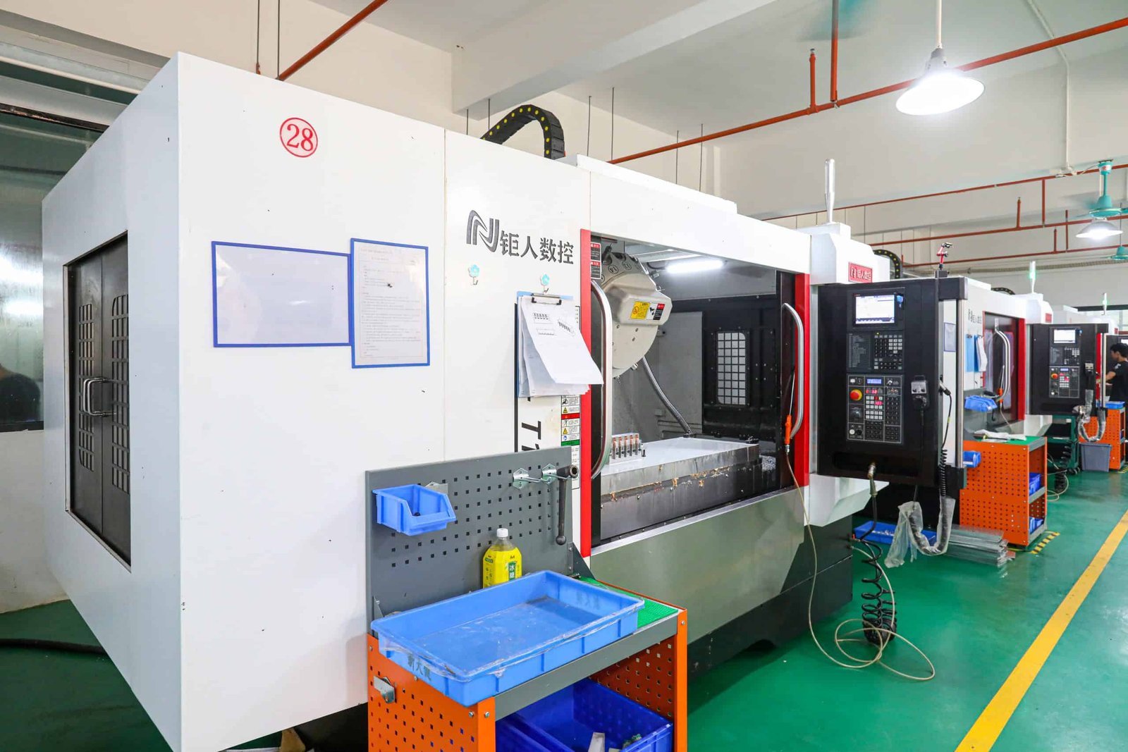
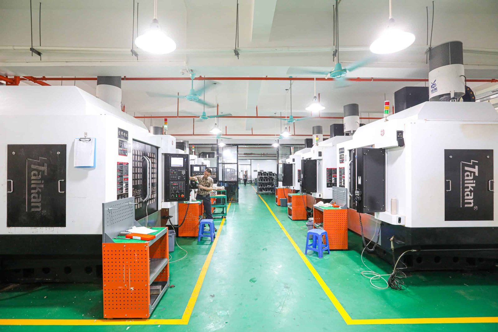
Our Shenzhen facility combines more than 140 CNC machines with dimensional inspection and finishing coordination, supporting opto-mechanical prototypes, design iterations, and repeat small batches for international engineering teams.
Request Precision Opto-Mechanical Parts
Upload your CAD model and drawing. Include the assembly function, critical optical interfaces, datum scheme, material, finish, quantity, cleanliness, inspection needs, and delivery target.
Optical machining questions
CNC Precision Optics FAQ
What optical-system components can 6CNC machine?
Typical parts include lens barrels, retaining rings, lens cells, mirror mounts, camera housings, sensor brackets, stages, apertures, baffles, spacers, adjustment parts, instrument bases, and alignment fixtures.
Does 6CNC manufacture optical glass lenses?
Our standard scope is CNC-machined opto-mechanical metal and plastic hardware. Optical glass generation, grinding, polishing, coating, and optical-performance certification require specialized processes and must be reviewed separately.
Which materials are used for precision optics hardware?
Aluminum, stainless steel, titanium, copper alloys, and engineering plastics are common. Selection depends on stiffness, mass, thermal expansion, conductivity, corrosion, cleanliness, outgassing, and finishing requirements.
Can you maintain alignment between bores and mounting faces?
Yes, within the capability confirmed for the specific geometry and drawing. Clearly identify the optical axis, datum structure, concentricity, runout, perpendicularity, position, and inspection requirements during quotation.
Do you support optical prototypes and small batches?
Yes. We support one-off development parts, design variants, alignment fixtures, validation builds, and repeat small batches.
What files are needed for a quote?
Send a 3D CAD model and dimensioned drawing with material, quantity, GD&T, optical-interface datums, finish, masking, cleanliness, inspection requirements, and delivery destination.
Latest insights
Related CNC Resources
Why Are Stratasys Printers So Expensive?
Compare industrial 3D printing considerations for prototype programs.
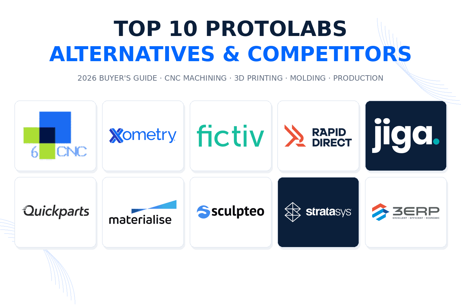
Top 10 Protolabs Alternatives & Competitors
Compare suppliers for prototypes and production parts.

Why Is Xometry So Expensive?
Understand marketplace pricing and direct CNC alternatives.