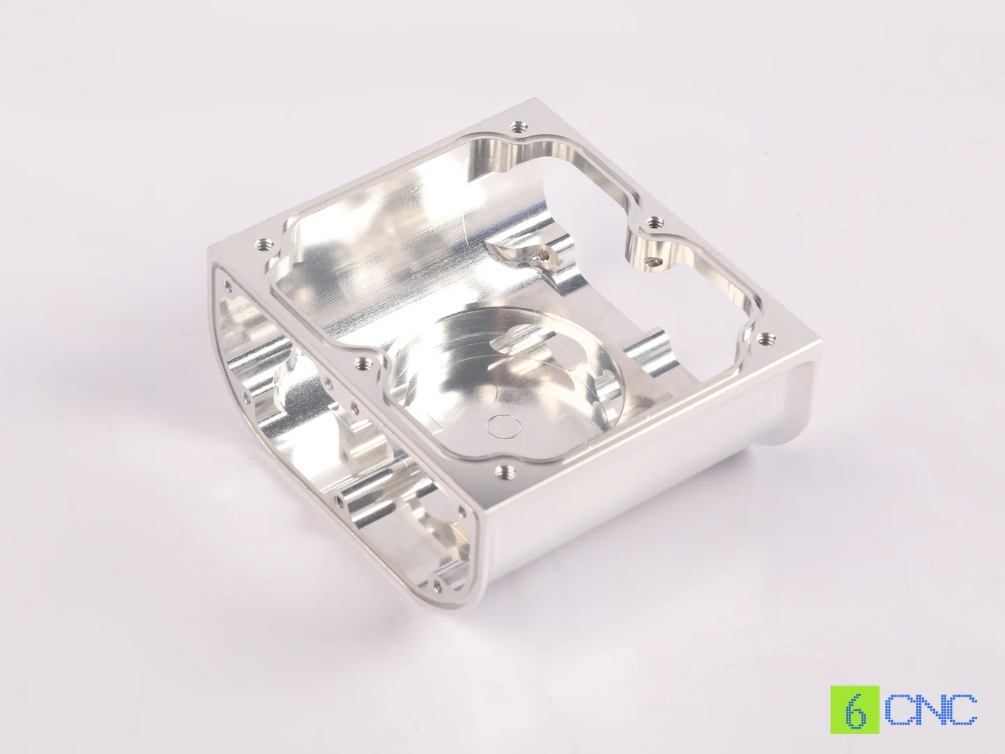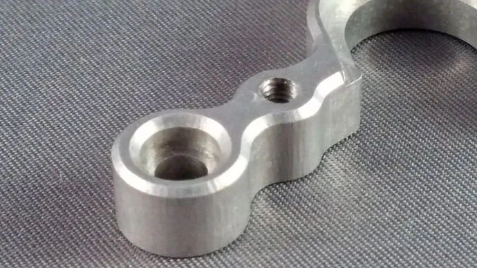
A drawing for an optical component can look surprisingly ordinary. It may contain several bores, mounting faces, threads, pockets, and perhaps one curved surface. But once those features begin controlling the position of a lens, sensor, mirror, or light path, the manufacturing problem changes.
A lens barrel may meet every individual diameter tolerance and still fail if its lens seats do not share the same axis. A mirror mount may be dimensionally correct but distort the mirror after assembly. A reflector can have the right overall dimensions while small surface-form errors change its light distribution. An optical mold may look excellent visually, yet reproduce the same microscopic form error into every molded lens.
This is the real challenge of optical precision machining. The objective is not simply to manufacture a part with small tolerances. It is to preserve the geometric relationships that allow the optical system to perform as designed.
That also means there is no single process called “optical machining.” A lens barrel, an optical housing, a freeform reflector, and an optical mold insert may all belong to the same system while requiring completely different manufacturing routes.
Start by Identifying What the Part Does in the Optical System
The most useful first step is to separate optical components by function rather than by how complicated their CAD models look.
| Part type | Typical components | Main manufacturing concern | Common process |
|---|---|---|---|
| Optomechanical structure | Housings, brackets, sensor mounts, optical benches | Position, flatness, perpendicularity, stability | CNC milling / 5-axis machining |
| Axis-alignment component | Lens barrels, lens seats, spacers, retaining rings | Coaxiality, runout, bore size, shoulder position | Precision turning / boring |
| Functional optical surface | Mirrors, reflectors, some light guides | Surface form, waviness, roughness | Precision machining + polishing or ultra-precision machining |
| Optical replication tooling | Mold inserts, freeform molds, Fresnel tooling | Form accuracy, micro-features, surface finish | Diamond machining / grinding / polishing |
This distinction matters because most components inside an optical product are not themselves optical surfaces. A camera housing, laser bracket, or lens barrel may require very precise mechanical relationships but never require a nanometer-scale finish.
By contrast, when the machined surface directly reflects, refracts, or distributes light, surface form and texture become part of the optical design itself.
Optical Precision Is Usually a Combination of Three Different Requirements
One reason optical parts are easily over-specified is that “precision” gets treated as a single number. In practice, there are usually three different levels of control.
The first is dimensional precision: diameters, lengths, thicknesses, hole sizes, thread dimensions, and pocket depths. These determine whether the component physically fits and assembles correctly.
The second is geometric and alignment precision. This is often more important for optomechanical components. A drawing may need to control runout of a lens seat, perpendicularity of a locating shoulder, position of a sensor plane, parallelism between mounting faces, or coaxiality between several bores. A component can meet every individual ± dimension and still fail at this level.
The third is optical surface precision. When the surface itself controls light, requirements may include form error, waviness, mid-spatial-frequency error, and nanometer-scale roughness. At this point, conventional precision CNC machining and true ultra-precision optical machining become different manufacturing disciplines.
A normal high-end CNC machining center can produce excellent dimensional and geometric accuracy. That does not automatically mean it can produce an optical mirror surface or a sub-micron freeform mold.
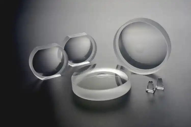
Lens Barrels Show Why Alignment Often Matters More Than a Tight Diameter
A lens barrel is one of the clearest examples of how optical component machining differs from general-purpose turning.
Imagine a barrel containing three lens seats. Each internal diameter is individually within tolerance, but the first bore is slightly shifted in one direction, the second shifts in another, and one locating shoulder is not perfectly perpendicular to the barrel axis. Every individual dimension may pass, yet the optical stack can still be misaligned.
For this reason, the manufacturing strategy should focus on the relationship between the lens-locating features, not simply their individual dimensions.
Where geometry allows, several critical internal diameters and shoulders should be machined from the same rotational reference and with as few unnecessary re-clamping operations as possible. A typical process may combine precision turning, boring, shoulder machining, thread cutting, and final runout inspection around one functional axis.
The lens seat itself usually has two jobs. The bore establishes radial position, while the shoulder establishes axial position. The bore therefore may need controlled diameter and runout, while the shoulder may need flatness and perpendicularity. Tightening one tolerance while ignoring the other does not necessarily improve the optical assembly.
This is also why a drawing should communicate the functional datum structure clearly. If several lens seats are supposed to share the same optical axis, that relationship matters more than putting an unusually tight ± tolerance on every diameter.
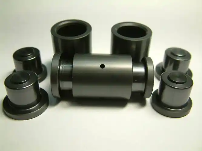
Optical Housings Are Often Limited by Part Stability Rather Than Machine Accuracy
Optical equipment frequently uses aluminum housings because aluminum is lightweight, easy to machine, thermally conductive, and compatible with finishes such as black anodizing.
But optical housings are also commonly designed with deep pockets, large amounts of material removal, and thin walls. That creates a manufacturing problem that has little to do with the nominal positioning accuracy of the CNC machine.
When a thick aluminum billet is converted into a lightweight housing, internal residual stresses can redistribute. The part may bow, twist, or move after it is removed from the fixture. A thin wall can also deform under clamping pressure and spring back after machining.
For critical optical interfaces, a more stable route may involve rough machining first, allowing the part to stabilize, and then semi-finishing and finishing the important datum surfaces later. The goal is not simply to machine the feature accurately while it is clamped; the part must remain accurate after it is released and assembled.
This becomes especially important when the housing establishes the relationship between a lens, image sensor, mirror, or laser source.
A CNC machine can only cut the geometry presented to it. If the workpiece itself changes shape after machining, process sequencing and workholding become part of the precision strategy.
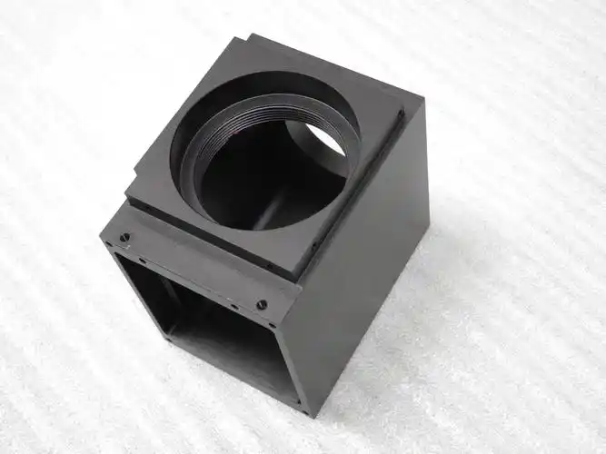
Mirror Mounts Add Assembly Distortion to the Problem
A mirror mount can pass inspection and still create an optical problem during assembly.
If the mirror sits against a mounting surface and is secured by screws or clamps, the contact geometry and fastening forces can distort the optic. A very small deformation may be irrelevant for a mechanical cover but significant in an optical system.
This means the manufacturer may need to consider flatness, contact area, fastener position, material stiffness, and clamping behavior together. In other words, assembly behavior becomes part of dimensional performance.
This is one reason optical precision machining benefits from understanding the part’s function rather than treating the drawing as a collection of unrelated tolerances.
Precision Reflector Machining Is a Different Class of Work
Reflectors move the project from optomechanical machining into functional optical surface manufacturing.
An aluminum reflector might be spherical, parabolic, elliptical, aspheric, or fully freeform. Here, the machined surface itself determines how light is redirected. Overall dimensions still matter, but the more important question becomes how closely the actual surface matches the theoretical optical geometry.
A realistic precision reflector machining route is usually staged. Most material is removed first without attempting to create the final optical finish. The component may then be allowed to stabilize before semi-finishing establishes near-final geometry. Only after this does the functional surface receive the final machining, grinding, polishing, diamond machining, or coating required by the specification.
This matters because a reflector can look shiny and still be optically wrong. A visually reflective surface may contain form error, waviness, or periodic tool marks that alter beam distribution or increase scattered light.
“Mirror finish” is therefore not a meaningful engineering requirement by itself. Optical surfaces need measurable specifications.
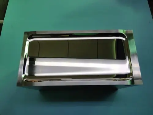
When Conventional CNC Machining Stops Being Enough
There is no single tolerance value that separates normal precision machining from ultra-precision optical manufacturing. The transition usually becomes clear from the function of the surface.
Conventional CNC machining is well suited to optical housings, mounts, barrels, sensor structures, and many reflector blanks. It can also produce complex 3D geometry that later receives another finishing process.
A different manufacturing route should be considered when the actual machined surface must directly provide optical performance and requires characteristics such as sub-micron form control, nanometer-scale roughness, extremely low waviness, or high-quality freeform optical geometry.
This is where processes such as single-point diamond turning (SPDT) become relevant.
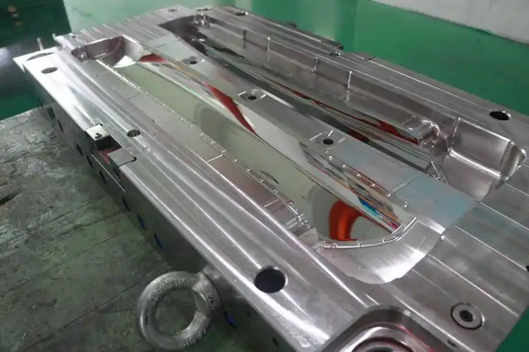
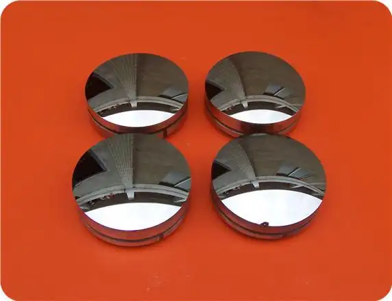
SPDT uses a single-crystal diamond tool together with an ultra-precision machine platform. On compatible materials, the process can directly generate optical-quality surfaces and may reduce or eliminate subsequent polishing. It is commonly associated with metal mirrors, infrared optics, aspheric surfaces, freeform components, and optical mold inserts.
But this capability should not be confused with ordinary CNC turning just because both processes use a rotating workpiece and a cutting tool.
Material Choice Can Determine the Manufacturing Route Before Machining Starts
For ordinary mechanical parts, material selection is usually dominated by strength, weight, corrosion resistance, cost, and availability.
For functional optical surfaces, machinability at the optical scale can become equally important.
Aluminum is widely used for optical housings, lens barrels, mirror substrates, telescope structures, and reflectors. For ordinary optomechanical parts, familiar alloys such as 6061 and 7075 may work well depending on mechanical requirements. But when the aluminum surface itself is diamond machined for optical use, alloy structure, inclusions, grain size, and material history can influence the achievable finish.
Copper and brass are also used in optical tooling and reflector applications, particularly where diamond-machining compatibility is valuable.
Optical molds often create another material problem. Steel is desirable for strength and durability, but conventional diamond cutting is poorly suited to ferrous materials. One common solution is to use a steel substrate coated with high-phosphorus electroless nickel, creating a surface that can be diamond machined while retaining the structural advantages of the steel underneath.
Transparent polymers such as PMMA and polycarbonate require an entirely different approach. They can be CNC machined for light guides, transparent prototypes, covers, or certain optical geometries, but heat, tool sharpness, internal stress, scratching, whitening, and melting all become important. A plastic component can be dimensionally perfect and still be optically unusable.
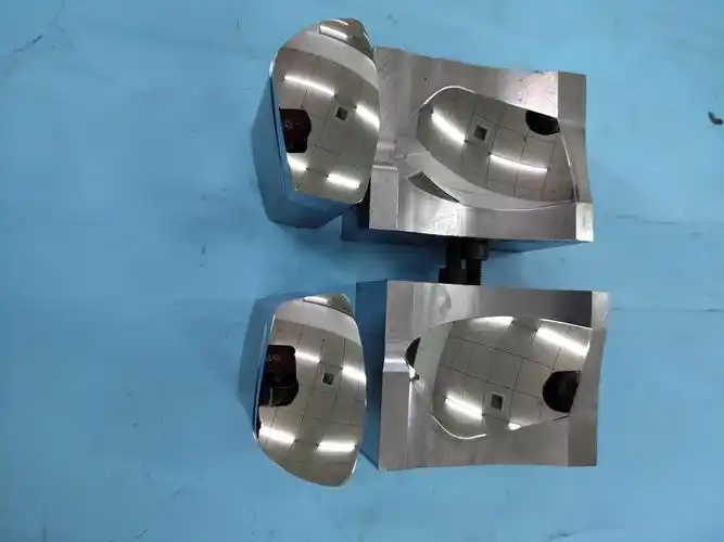
Optical Mold Machining Has an Extra Risk: Every Error Can Be Replicated
An optical mold insert is not simply another precision tool.
Any form error, tool mark, waviness, or micro-feature error present in the mold can be transferred into every replicated optical component. That makes optical mold machining especially sensitive to manufacturing and inspection.
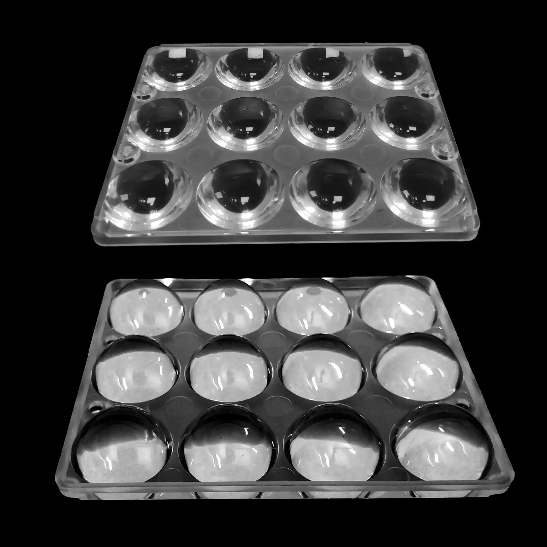
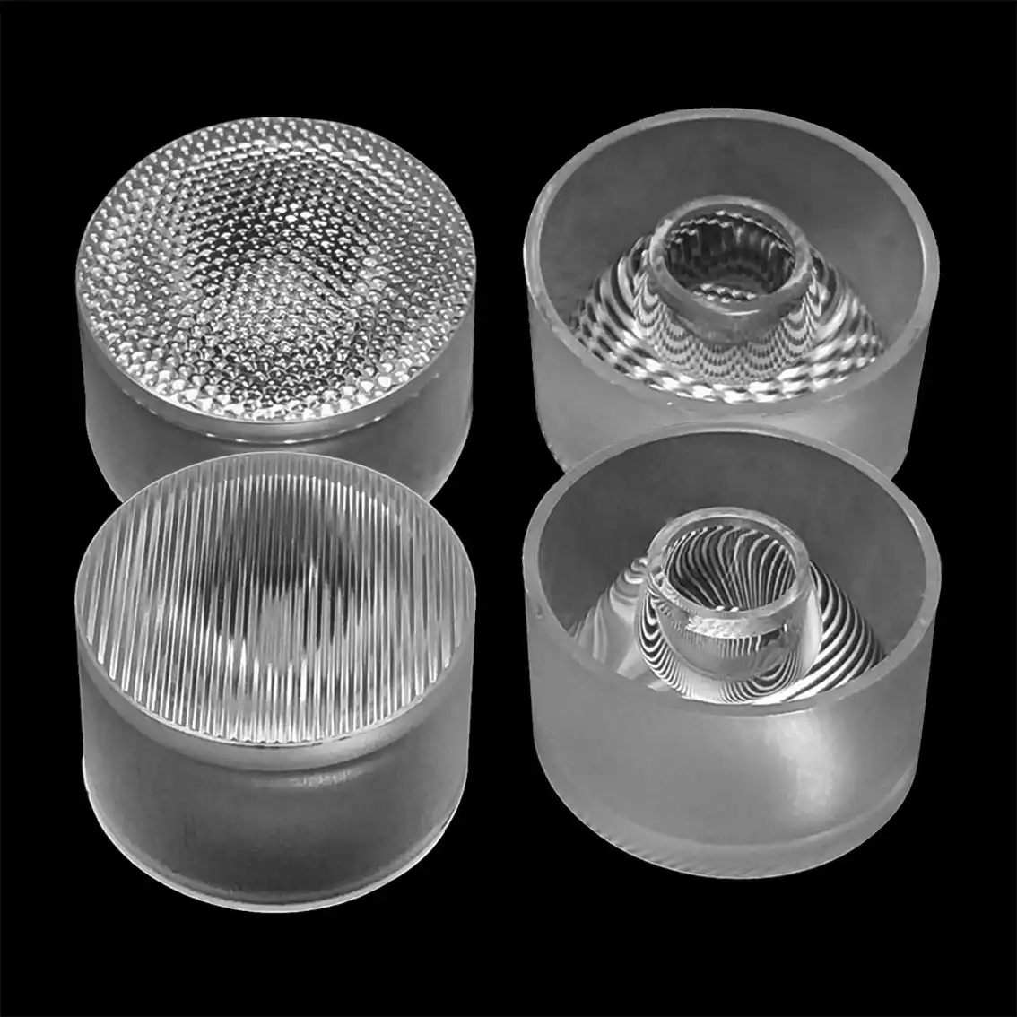
Typical applications include light guides, Fresnel lenses, automotive lighting components, head-up displays, AR/VR optics, and other freeform molded elements.
The manufacturing process may combine a stable mold substrate, precision coating, diamond turning or grinding, polishing, and optical metrology. For complex freeform designs, the mold itself may have no simple rotational symmetry, so its surface must be generated directly from a sophisticated CAD or optical definition.
The economic consequence is also different from a normal machined component: a small error in one custom part affects one part, while a small error in a mold can affect an entire production run.
Freeform Optics Change the Problem From “Tolerance” to Surface Control
Modern optical systems increasingly use freeform surfaces because they can reduce component count, improve packaging, and correct optical aberrations more efficiently than traditional spherical geometry.
They are now common in applications such as automotive lighting, head-up displays, compact imaging systems, AR/VR, and aerospace optics.
Manufacturing these surfaces is difficult because the machine must reproduce a continuously changing three-dimensional optical form while also controlling surface texture. Specialized ultra-precision systems may use technologies such as slow-tool servo or fast-tool servo to produce non-axisymmetric surfaces that cannot be generated through ordinary rotational turning.
This is a fundamentally different problem from simply machining a complex 5-axis mechanical surface.
5-Axis CNC Is Valuable in Optical Manufacturing—But for a Different Reason
5-axis machining is very useful for optomechanical parts because it reduces setups.
An optical housing may contain an angled sensor face, several mounting surfaces, complex pockets, an optical-axis bore, and a mirror interface. If these features can be machined with fewer re-clamping operations, the relationship between them can be maintained more reliably.
That is the real value of 5-axis machining in many optical projects.
It does not mean a conventional 5-axis machining center automatically produces optical-grade mirror finishes or nanometer-level surface form.
The number of machine axes and the level of ultra-precision surface capability are separate questions.
For Optical Surfaces, Ra Is Only One Part of the Specification
Mechanical machining discussions often reduce surface quality to Ra.
Optical surfaces need a broader view.
Imagine two reflectors with exactly the same measured Ra. One closely follows the designed optical surface. The other contains a slow wave across its profile. They can perform very differently.
A useful way to think about optical surface errors is:
| Error scale | What it describes | Possible effect |
|---|---|---|
| Form error | Large-scale deviation from theoretical surface | Focus, beam direction, wavefront |
| Waviness / mid-spatial error | Intermediate repeating surface patterns | Contrast, scatter, imaging artifacts |
| Surface roughness | Fine surface texture | Light scattering, optical efficiency |
This is why a drawing that only specifies an extremely small Ra value may still fail to communicate what the optical designer actually needs.
The specification should match the way the surface functions.
Metrology Must Match the Type of Precision Being Controlled
There is no single inspection machine that verifies every optical component requirement.
A CMM is excellent for measuring housing geometry, mounting holes, datum positions, lens-seat locations, and other mechanical features. Bore gauges, micrometers, and roundness equipment may be appropriate for other precision dimensions.
Surface texture may require profilometry.
Functional optical surfaces may require interferometry or specialized form measurement capable of comparing the manufactured surface against its theoretical optical form.
This is one of the most important rules in optical precision machining:
A tolerance is only meaningful if there is a suitable way to verify it.
The measurement method should therefore be considered when the requirement is created—not after the part has already been machined.
A Better Optical Drawing Focuses on Functional Relationships
Optical parts often become unnecessarily expensive because every surface receives a tight tolerance.
A better drawing makes clear which features actually control the system.
Consider an aluminum lens housing. The drawing might establish the primary mounting face as Datum A and the optical-axis bore as Datum B. Critical lens seats could then be controlled relative to Datum B, while the sensor mounting surface receives the necessary position and perpendicularity requirements.
Nonfunctional exterior geometry can remain under normal machining tolerance.
This approach communicates more manufacturing information than placing ±0.01 mm on every feature.
The same principle applies to functional optical surfaces. A reflector should not simply be labeled “mirror finish.” Its actual form, roughness, coating, and inspection requirements should be defined according to the optical design.
Surface Treatments Need to Be Included in the Tolerance Strategy
Many optical mechanical components are finished after machining.
Black anodizing is particularly common on aluminum because it provides corrosion resistance, appearance, and reduced internal reflections. Other projects may use electroless nickel, hard anodizing, passivation, or reflective coatings.
These processes can change dimensions or surface behavior.
Critical fits may need masking. Coating thickness may need to be included in the dimensional allowance. Some important interfaces may require inspection after treatment rather than before it.
The finishing process should therefore be planned together with machining, not added after the precision dimensions have already been finalized.
Prototype Optical Parts Should Not Always Receive Final Optical Finishing
Optical products often go through several design revisions.
An early build may exist mainly to confirm lens spacing, assembly, sensor position, focus mechanism, or package size. Applying expensive optical finishing to every early prototype can be unnecessary if the underlying mechanical design is still changing.
A more practical development route may be:
Mechanical prototype → alignment revision → engineering validation → optical finishing validation → small-batch production
This allows expensive finishing processes to be introduced only when the geometry is sufficiently stable.
It also helps separate two questions:
- Does the mechanism and optical architecture work?
- Can the final optical surfaces be produced consistently?
Treating those as separate validation steps can reduce unnecessary iteration cost.
Optical Projects Are Naturally Well Suited to Small-Batch Precision Manufacturing
Many optical products are not high-volume consumer devices. Scientific instruments, machine-vision systems, laser equipment, medical optical devices, robotics sensors, specialized cameras, and aerospace systems may require relatively small numbers of highly engineered components.
A typical project may progress from 3 prototype parts to 20 engineering units and later to repeat batches of 50 or 100 components.
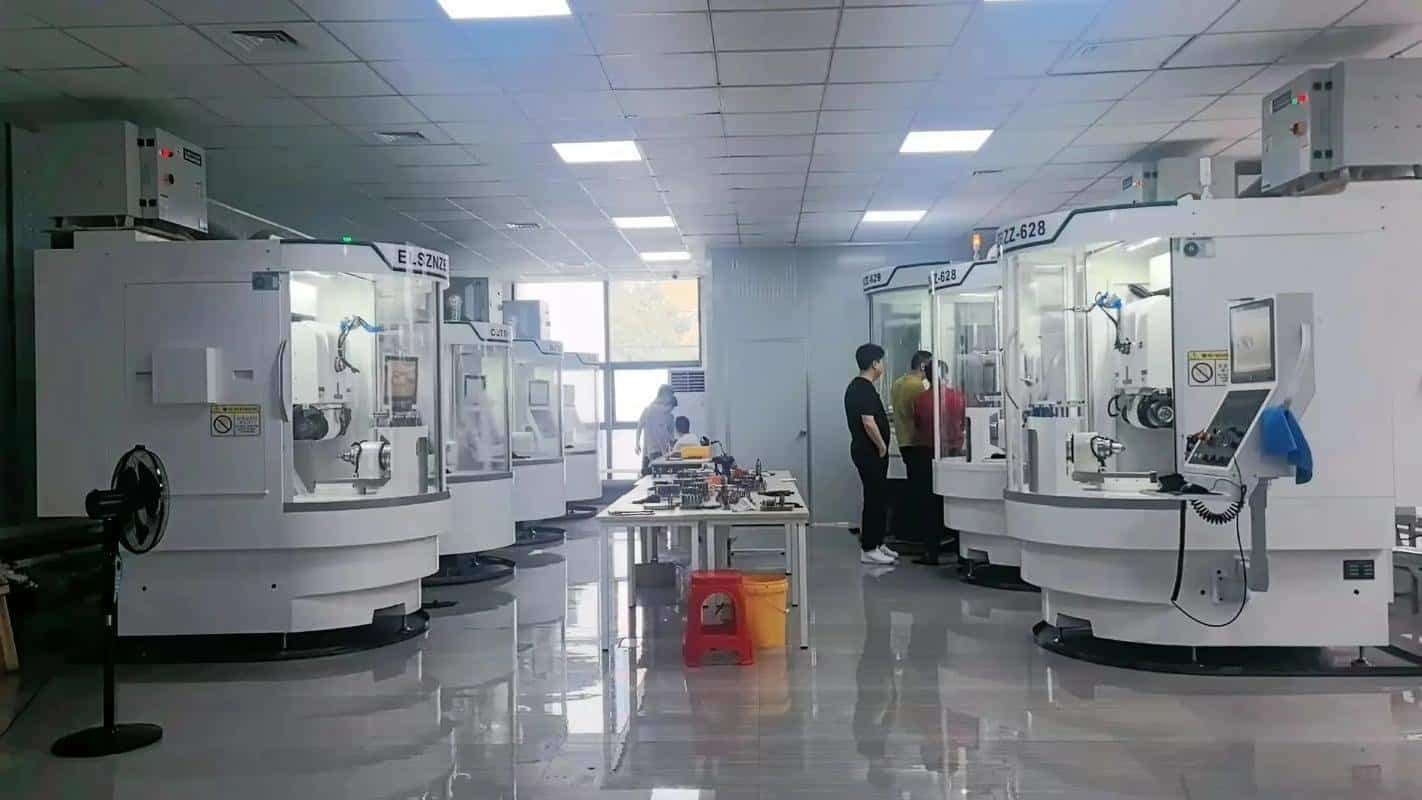
At that stage, the challenge changes. The supplier is no longer just trying to produce one good part. Fixtures, tool offsets, inspection methods, coating controls, and datum strategies need to reproduce the same optical relationships across every subsequent batch.
This is where small-batch custom precision machining becomes relevant to optical manufacturing.
For 6CNC, the strongest role is in custom optomechanical and precision components such as lens barrels, optical housings, sensor structures, mirror mounts, alignment components, precision reflectors, and related mechanical parts moving from prototype into repeatable small-batch production.
Where a component contains a true optical surface requiring diamond turning, ultra-precision polishing, or another specialized finishing process, that requirement should be identified separately during manufacturing review rather than treated as an ordinary CNC tolerance.
What Should Be Included in an Optical Component RFQ?
A useful optical machining RFQ should communicate more than material and nominal dimensions.
Include the 3D CAD model and 2D engineering drawing, but also make the functional relationships clear. Identify important datums, the optical axis where relevant, coating requirements, GD&T, and the specific surfaces that are optically functional.
For a true optical surface, additional information may include surface form, roughness, coating, optical cosmetic requirements, and the intended inspection method.
Most importantly, tell the manufacturer what each critical feature does.
Knowing that a surface locates a lens, establishes a sensor plane, supports a mirror, or directly reflects light can materially change the proposed manufacturing route.
Final Takeaway
The most useful question in optical manufacturing is not:
“How tight a tolerance can the machine hold?”
It is:
“Which geometric relationship actually determines whether the optical system works?”
For a lens barrel, that may be a common axis shared by several lens seats. For a camera housing, it may be the relationship between the lens axis and sensor plane. For a mirror mount, it may be mounting stability. For a reflector or optical mold, it may be the actual surface form rather than a conventional ± dimension.
Once those critical relationships are understood, the manufacturing route becomes much clearer.
Some components need precision turning or 5-axis CNC machining. Others require grinding, lapping, or polishing. True optical surfaces may require single-point diamond turning or another ultra-precision process.
Optical precision machining is therefore not about making every surface as precise as possible. It is about identifying the few surfaces and relationships that control optical performance—and building a manufacturing process capable of reproducing them reliably from prototype through small-batch production.