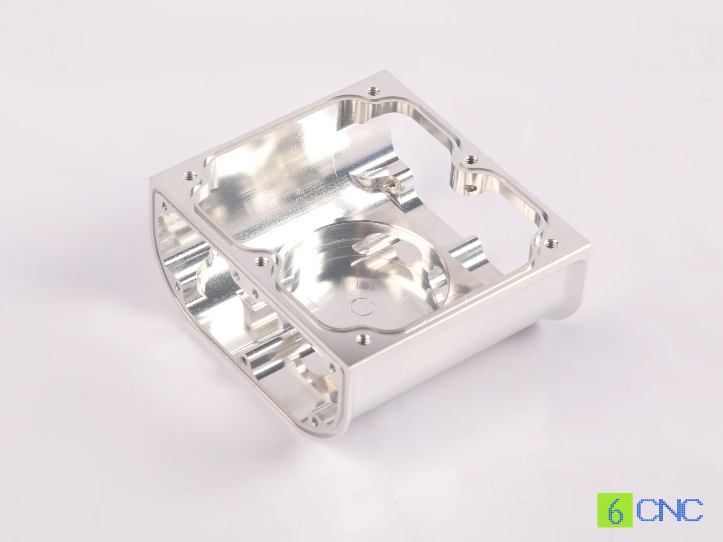
A beveled edge may look like a minor detail on a machined part, but in practice it can affect assembly, safety, edge strength, welding preparation, appearance, and manufacturing cost.
On a simple bracket, the bevel may only remove a sharp corner. On a shaft, it may help the part enter a bearing or seal. On a threaded hole, an angled lead-in can make assembly easier and protect the first thread. On a welded structure, a much larger bevel may control weld penetration. And on a complex housing, the bevel itself may become a tightly controlled functional surface.
This is why engineers should not treat every angled edge as the same feature.
The angle, width, location, tolerance, material, and function all influence how that edge should be designed and how the CNC shop should machine it.
This guide explains what beveled edges mean in CNC machining, how they differ from chamfers and fillets, common bevel types and angles, machining methods, drawing callouts, typical design mistakes, and how to choose an edge treatment that is both functional and economical to manufacture.
What Is a Beveled Edge in CNC Machining?
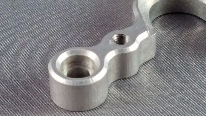
A beveled edge is an angled surface created between two adjacent surfaces of a machined component. Instead of the two surfaces meeting at a sharp corner, material is removed to create a sloped transition.
The bevel can be very small or relatively large.
A 0.5 mm × 45° edge break on an aluminum housing and a 10 mm-wide 30° welding bevel are both angled edge features, but they serve completely different functions and require different manufacturing strategies.
Common reasons for adding a beveled edge include:
- removing sharp edges;
- helping components enter mating features;
- protecting edges from damage;
- preparing components for welding;
- improving appearance;
- creating clearance;
- controlling contact between mating parts;
- preparing a thread or bore entrance;
- reducing burrs.
The main design question is therefore not simply:
“Should this part have a bevel?”
It is:
“What should this angled edge accomplish?”
That function should determine the geometry.
Bevel vs Chamfer: Are They the Same?
In machining discussions, the words bevel and chamfer are often used interchangeably.
There is no universal industry rule that completely separates them.
A chamfer is generally a flat angled cut that replaces a sharp corner, most commonly on a relatively small edge feature. A bevel is often used to describe a larger or more functionally important angled surface, particularly when the angle is not 45°.
For example:
- 0.5 × 45° around a machined housing: normally called a chamfer.
- 1 × 45° at the entrance to a bearing bore: usually called a chamfer.
- 30° angled edge across a thick plate: more likely called a bevel.
- 37.5° welding preparation: normally called a bevel.
- large decorative angled surface: commonly described as a bevel.
The geometry can therefore overlap.
From a CNC machining standpoint, what matters more than terminology is that the drawing clearly defines:
- the angle;
- size;
- location;
- tolerance;
- functional requirement.
If those are clear, the machine shop can manufacture the edge correctly regardless of whether the designer labels it “bevel” or “chamfer.”
Bevel vs Chamfer vs Fillet
Bevels and chamfers both create flat angled surfaces. A fillet creates a curved transition instead.
| Feature | Geometry | Typical purpose | Common machining method |
|---|---|---|---|
| Bevel | Flat angled surface | Functional angle, welding, fit, appearance | Chamfer mill, end mill, 4/5-axis machining |
| Chamfer | Usually smaller flat edge break | Deburring, assembly lead-in, edge protection | Chamfer mill |
| Fillet | Rounded transition | Stress reduction, smooth transition | Radius cutter, ball nose, form tool |
The difference becomes important when the edge carries structural load.
A fillet generally produces a smoother change in section than a sharp angular transition. For highly stressed components, a radius may therefore be more suitable than a bevel if the design objective is reducing local stress concentration.
A bevel, by contrast, may be more appropriate where a specific mating angle or clearance is required.
Common Types of Beveled Edges
Beveled edges can be classified according to how many surfaces are angled and how those surfaces relate to the part.
Single Bevel
A single bevel is machined on only one side of an edge.
This is the simplest arrangement and is commonly used for:
- assembly lead-ins;
- external edge treatment;
- welding preparation;
- panel edges;
- brackets.
For example, a steel plate may have a 30° bevel machined along one edge before welding.
Double Bevel
A double bevel creates angled surfaces on both sides.
This can be symmetrical or asymmetrical.
Typical uses include:
- welding joints;
- blade-like profiles;
- centered edge forms;
- specialized mating features.
Machining difficulty depends on whether both sides can be accessed in the same setup.
Compound Bevel
A compound bevel contains multiple angles or an angled surface that changes direction.
This may occur in:
- aerospace brackets;
- complex housings;
- tooling;
- multi-surface interfaces.
A basic 3-axis machine may require several setups to produce compound bevels. In some cases, 5-axis machining allows the cutter to maintain the required angle while following a more complex edge.
Interrupted Bevel
Some bevels do not run continuously around a part.
The angled feature may stop around:
- mounting tabs;
- ribs;
- bosses;
- pockets;
- ports.
Interrupted geometry makes tool entry and exit more important because the cutter cannot simply follow one continuous edge.
Common Bevel Angles
There is no single standard bevel angle for CNC machined parts.
45° is extremely common because standard chamfer tools are widely available, but many functional bevels use other angles.
Typical angles include:
| Angle | Typical application |
|---|---|
| 15°–30° | Shallow lead-in or guided assembly |
| 30° | Thread starts, specialized mating features, some weld preparations |
| 45° | General chamfering, edge break, assembly |
| 60° | Fastener-related geometry, countersink-related features |
| Custom | Functional interfaces, welding, specialized part geometry |
The correct angle should come from the function.
For instance, a 45° chamfer is convenient to machine, but if the mating component approaches at 20°, using a 45° edge may provide very little guidance.
Likewise, welding specifications may require an exact groove angle rather than whichever cutter happens to be available.
Bevel Size Matters as Much as Bevel Angle
Specifying only an angle is usually not enough.
A designer should also define the size or location of the angled surface.
For a 45° chamfer, the callout may simply be:
1 × 45°
For other bevels, the drawing may specify:
- angle and one linear dimension;
- two endpoint dimensions;
- included angle and land;
- depth relative to a datum.
A larger bevel removes more material and may change the local wall thickness or structural behavior.
For example, adding a 4 mm bevel around a 5 mm-thick wall is not a minor cosmetic change. It can remove a significant portion of the section.
This is why bevel size should be reviewed in relation to the surrounding geometry.
Why Beveled Edges Are Used in CNC Parts
1. To Improve Assembly
A sharp 90° edge can catch on a mating part.
A bevel acts as a lead-in.
This is common on:
- shafts;
- bores;
- pins;
- bushings;
- connectors;
- housings.
Imagine inserting a precision shaft into a bearing.
If the shaft ends in a sharp corner, even slight misalignment can damage the bearing or create difficulty during assembly.
A small chamfer helps guide the shaft into the bore.
2. To Protect Edges
Sharp machined corners can chip or deform during handling.
A small edge break removes the most vulnerable tip.
This is especially useful on aluminum components where thin sharp edges can become damaged during transport or assembly.
3. To Remove Burrs
Machining operations often leave small burrs along exposed edges.
A controlled chamfer can remove those burrs while creating a defined edge condition.
This is preferable to vague instructions such as “deburr all edges” when edge size matters.
4. To Prepare for Welding
Welding bevels are usually much larger than ordinary CNC chamfers.
They help create a groove where weld material can penetrate deeply into thick sections.
Typical variables include:
- bevel angle;
- root face;
- root opening;
- plate thickness.
These dimensions should follow the welding design rather than general CNC edge-break practice.
5. To Create Functional Clearance
A bevel may provide clearance for another component.
For example, a mounting block may need a beveled corner so it clears a fillet or adjacent structure.
6. To Improve Appearance
Large bevels are sometimes deliberately used as visual design features.
This is common in:
- consumer electronics;
- camera hardware;
- instrument panels;
- premium aluminum housings.
Cosmetic bevels often require more attention to tool marks, edge continuity, and anodizing appearance than a normal deburring chamfer.
How CNC Machines Cut Beveled Edges
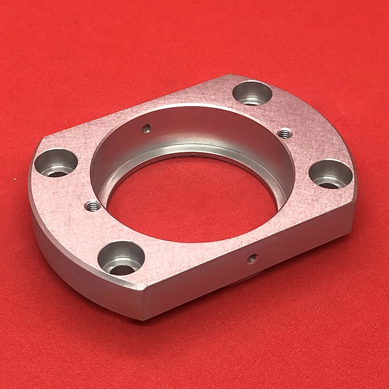
The machining method depends on the size, angle, accessibility, and geometry of the bevel.
Chamfer Milling
A chamfer mill is the most common tool for small and medium-sized bevels.
The cutter contains a defined cutting angle.
Typical tools include:
- 45° chamfer mills;
- 30° tools;
- 60° tools;
- 90° included-angle tools;
- countersink tools.
The CNC program positions the tool so that the cutting edge removes the required amount of material.
This method is efficient for:
- external edges;
- hole entrances;
- pocket edges;
- standard edge breaks.
For small bevels, it is usually the simplest and most economical option.
End Milling With Toolpath Geometry
A bevel can also be produced using an end mill.
Instead of relying on the cutter angle, the machine moves the tool along a programmed angled surface.
This can be useful when:
- the bevel is large;
- a specialized chamfer tool is unavailable;
- the feature is part of a larger angled surface.
However, several passes may be required to achieve a smooth finish.
Ball Nose Milling
Ball nose end mills can machine more complex transitions where a bevel blends into curved geometry.
They are not normally the most efficient tool for a simple straight bevel, but they become useful when the surrounding surface is already freeform.
4-Axis and 5-Axis Bevel Machining
Multi-axis machining becomes valuable when the beveled edge cannot be conveniently accessed from one fixed tool orientation.
Consider an aerospace housing with large bevels along edges pointing in several different directions.
A 3-axis machine may require:
- machine top bevel;
- reposition part;
- machine side bevel;
- reposition again;
- machine angled feature.
A 5-axis machine can rotate the workpiece while preserving the same primary setup.
This can improve both efficiency and feature-to-feature consistency.
For compound or curved bevels, simultaneous five-axis motion may be used if the cutter angle needs to change continuously along the edge.
Most normal chamfers, however, do not require 5-axis machining.
Using five axes for a simple 45° edge break would add unnecessary process complexity.
External Edge Bevels
External bevels are generally the easiest to machine because the tool has open access.
A chamfer mill can follow the outer profile of the part.
Common examples include:
- aluminum housings;
- brackets;
- mounting plates;
- covers.
The main concerns are usually:
- consistent chamfer width;
- corner transitions;
- burr control;
- tool marks.
On cosmetic parts, even a small variation in bevel width can be visually obvious.
Beveling Holes and Bores
Chamfers at hole entrances are extremely common.
They can:
- remove drilling burrs;
- create thread lead-ins;
- help pins enter;
- protect sealing components;
- prepare countersinks.
A typical tapped hole may include a small chamfer at the opening so that the first thread does not begin directly at a sharp edge.
A bearing bore may use a lead-in chamfer to simplify assembly.
However, the chamfer should not extend too far into a precision fit.
For example, an oversized chamfer on a short bearing seat can reduce the effective support length of the bore.
Thread Lead-In Chamfers
Thread starts benefit from a controlled lead-in.
A sharp thread beginning directly at the face can be easily damaged and may make assembly more difficult.
A chamfer removes the incomplete first thread and provides a smoother starting condition.
The appropriate angle and depth depend on:
- thread diameter;
- thread pitch;
- internal or external thread;
- mating component.
The designer does not necessarily need to specify every thread-start chamfer individually if a recognized thread standard or shop practice governs the feature, but critical applications should be explicit.
Bevels on Thin-Wall Parts
Beveling thin walls requires more care than beveling a solid block.
A relatively large bevel can remove a substantial percentage of the wall thickness.
The cutting force may also push or vibrate the thin section.
Possible problems include:
- wall distortion;
- inconsistent bevel width;
- chatter;
- edge deformation.
A lightweight aluminum housing with a 1 mm wall should not automatically receive the same 1 mm × 45° chamfer used on a thick structural plate.
The edge treatment should be scaled to the section thickness.
Cosmetic Bevels on Aluminum Parts
Cosmetic bevels deserve special attention because reflected light makes inconsistency obvious.
Imagine a black anodized aluminum electronics housing with a bright machined bevel running around the perimeter.
A 0.1 mm difference in bevel width may be much more noticeable visually than a similar dimensional variation elsewhere on the part.
Surface continuity can also matter.
If the tool enters and exits the bevel several times, visible witness marks may appear.
For premium cosmetic components, the process may require:
- a dedicated finishing tool;
- consistent cutter direction;
- controlled tool wear;
- continuous toolpaths;
- additional inspection of appearance.
This is very different from simply “breaking the edge.”
Beveling Aluminum
Aluminum alloys such as 6061 and 7075 are generally easy to bevel.
Sharp carbide tools can produce clean edges at relatively high cutting speeds.
The main problems include:
- built-up edge;
- burr formation;
- cosmetic tool marks.
A worn chamfer tool may smear aluminum rather than cut it cleanly.
For appearance-critical bevels, a fresh finishing tool can make a significant difference.
Beveling Stainless Steel
Stainless steel typically produces higher cutting forces and more heat.
If the chamfer tool rubs rather than cuts, the material may work harden locally.
Sharp tooling and stable feed are important.
Large bevels may require several passes rather than one heavy cut.
Burr formation can also be more persistent than in aluminum.
Beveling Titanium
Titanium bevels are generally machined using conservative, stable cutting conditions.
Heat management and tool wear become more important.
A large bevel removes more material than a small edge chamfer, so the process should be treated like a real machining operation rather than a minor finishing pass.
Beveling Engineering Plastics
Plastics such as POM, PEEK, nylon, PTFE, and polycarbonate behave very differently from metals.
Some are relatively flexible.
Others can soften under heat.
A dull cutting tool can deform or smear the edge rather than produce a clean bevel.
Sharp tooling and controlled cutting temperature are particularly important.
Thin plastic edges may also move during machining, so workholding and part support matter.
Bevels and Surface Finishing
Bevel geometry can affect how a part looks after secondary finishing.
Anodizing
A beveled aluminum edge generally anodizes along with the rest of the part unless it is machined after anodizing.
Sharp corners tend to receive thinner anodic coating than broad surfaces, so breaking the edge can sometimes improve finish consistency.
Plating
Large bevels can change current distribution during electroplating.
Critical edge geometry should therefore be considered together with coating thickness.
Bead Blasting
Bead blasting softens the visual appearance of machined surfaces and can make small tool marks less visible.
However, it will not correct geometric inconsistency in the bevel itself.
How to Specify a Beveled Edge on an Engineering Drawing
Ambiguous edge callouts cause unnecessary questions and production mistakes.
A good drawing should define the geometry clearly.
45° Chamfer
A common callout is:
1 × 45°
This means a 1 mm chamfer at 45°.
Custom Angle Bevel
A non-45° bevel may require both:
- angle;
- linear size.
For example:
2 mm × 30°
The reference direction should be unambiguous.
General Edge Break
A drawing may include a note such as:
BREAK SHARP EDGES 0.2–0.5 mm
This is useful for noncritical edges where exact chamfer size does not matter.
It should not be used when the bevel performs a functional role.
Weld Bevel
Weld preparation should define the complete joint geometry, which may include:
- bevel angle;
- root face;
- groove angle;
- root gap.
Simply writing “bevel edge” is not sufficient.
Why “Deburr All Edges” Can Be Too Vague
“Deburr all edges” is common on engineering drawings.
It tells the manufacturer to remove burrs but does not necessarily define the final edge geometry.
Two machinists may interpret it differently.
One may remove only the loose burr.
Another may create a visible 0.5 mm chamfer.
If edge appearance or function matters, specify the edge break directly.
For example:
BREAK SHARP EDGES 0.2–0.3 mm
gives the shop a clearer target.
Common Bevel Design Mistakes
Making Every Edge the Same Size
A large structural edge and a 1 mm thin wall do not necessarily need the same chamfer.
Apply edge treatment according to geometry and function.
Specifying an Unnecessary Custom Angle
A 43° bevel may be perfectly machinable, but if there is no functional reason for 43° instead of 45°, it may require a special tool or more complex toolpath.
Standard angles are usually more economical.
Oversizing Hole Chamfers
A large chamfer around a precision bore can reduce effective bearing or sealing length.
Ignoring Tool Access
An internal bevel may be easy to draw but difficult for the cutter and holder to reach.
Over-Tolerancing Cosmetic Bevels
If the bevel exists only to remove a sharp edge, assigning a very tight width tolerance adds unnecessary inspection and machining cost.
Under-Specifying Functional Bevels
The opposite problem is equally common.
If a bevel controls assembly or welding but the drawing only says “deburr,” the supplier has no reliable way to know the intended geometry.
Bevel vs Fillet for Stress Reduction
Bevels are sometimes described as a way to reduce stress concentration.
This needs context.
Removing a sharp external corner may reduce edge sensitivity, but a fillet usually provides a smoother load transition than an angular bevel when structural stress concentration is the main concern.
For example, at the inside corner between a thick bracket wall and base, a generous fillet is usually more structurally meaningful than a flat chamfer.
The correct choice depends on:
- load direction;
- geometry;
- material;
- fatigue requirements.
Do not add a bevel simply because it is assumed to make the part “stronger.”
Bevel vs Radius for Assembly
For assembly lead-ins, both bevels and radii can work.
A chamfer is easy to define and machine.
A radius provides a smoother transition.
For example, a pin entering a bore may use a 30° or 45° lead-in chamfer because it provides a predictable guiding geometry.
A sliding component exposed to repeated contact may benefit from a rounded edge to reduce localized wear.
The correct geometry depends on the mating condition.
Bevel vs Countersink
A countersink is a conical feature around a hole, typically designed for a fastener head or similar component.
It may look like a bevel, but it is functionally different.
For example:
- small 0.5 × 45° edge around a hole: chamfer;
- 90° conical seat for a flat-head screw: countersink.
Countersinks often require tighter control because the fastener seating depth depends on the cone geometry.
Bevel vs Deburring
Deburring removes unwanted material created during machining.
Beveling creates an intentional geometry.
These may happen in the same operation, but they are not the same requirement.
A chamfer mill can remove the drilling burr around a hole while simultaneously producing a specified 0.3 mm chamfer.
If the drawing only requires burr removal, however, the manufacturer should avoid removing unnecessary material.
When 5-Axis Machining Is Actually Useful for Beveled Edges
Most beveled edges do not justify 5-axis machining.
A standard 45° chamfer on a plate is trivial on a 3-axis machine.
Five-axis machining becomes useful when:
- bevels appear on many different faces;
- the part is difficult to reposition;
- feature-to-feature relationships must remain accurate;
- the bevel follows complex curved geometry;
- the bevel angle changes along the edge;
- toolholder clearance is limited.
Consider a robotic housing with angled surfaces on five sides.
Machining every bevel on a 3-axis machine might require several setups.
A 5-axis machine can reposition the component and machine those edges while maintaining one primary workholding condition.
The advantage is therefore not that the bevel itself is difficult.
It is that the overall part geometry is difficult.
Example: Beveled Bearing Housing
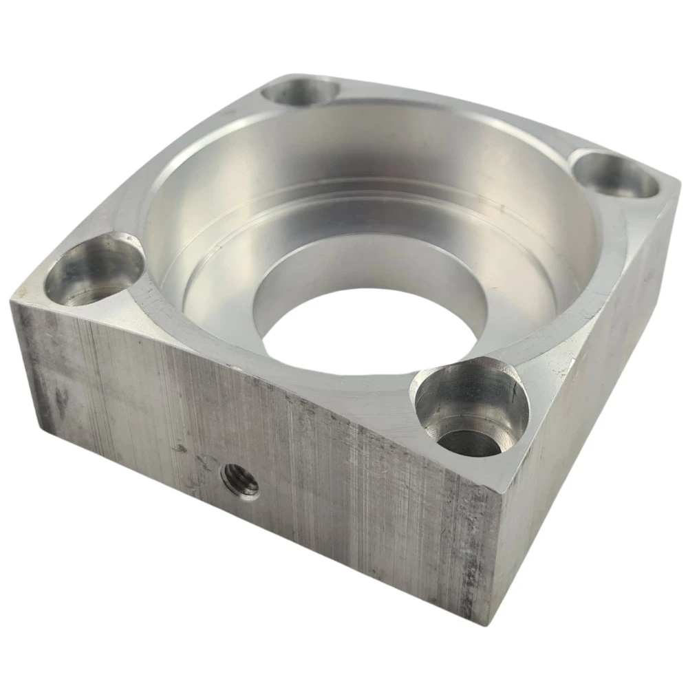
Consider a 7075 aluminum bearing housing.
The component contains a precision bore and a 1 × 45° lead-in chamfer.
The purpose of the chamfer is to guide the bearing during assembly and protect the sharp entrance to the bore.
The machining sequence might be:
- rough machine the bore;
- finish the bore to size;
- machine the lead-in chamfer;
- inspect bore diameter;
- inspect chamfer where function requires.
The chamfer should not be excessively large because it would reduce the effective axial length of the bearing seat.
This is a simple feature, but its size is directly related to function.
Example: Cosmetic Bevel on an Aluminum Housing
Now consider a consumer or optical electronics housing machined from 6061 aluminum.
The outside perimeter contains a 2 mm bevel used primarily as a visual design feature.
Unlike the bearing example, the main requirement may be appearance rather than fit.
The process should focus on:
- consistent width;
- smooth corner transitions;
- minimal witness marks;
- stable anodizing appearance.
The CNC shop might use a dedicated finishing tool after the main geometry is complete.
That same 2 mm bevel therefore requires a different machining priority even though the geometry is similar.
Example: Welding Bevel on a Steel Component
A thick steel component may require a 30° or 37.5° bevel along one edge before welding.
This bevel is much larger than a normal CNC chamfer.
The important variables may include:
- angle;
- root face;
- consistency along the joint;
- surface condition.
Machining may use:
- an angled end mill;
- a dedicated bevel cutter;
- a multi-axis setup.
The purpose is not cosmetic.
The geometry influences weld preparation and therefore should follow the welding specification.
Cost Factors for Beveled CNC Edges
A small standard chamfer usually adds little cost when the part is already being machined.
Cost increases when the bevel involves:
- custom angles;
- large material removal;
- multiple orientations;
- tight tolerances;
- cosmetic finish;
- difficult internal access;
- dedicated inspection.
A 0.5 × 45° edge break around an accessible housing may take seconds.
A 12 mm compound bevel running around several faces of a titanium component can be a significant machining operation.
The term “bevel” therefore does not describe machining cost by itself.
DFM Guidelines for Beveled Edges
A few simple rules improve both function and manufacturability:
Use standard angles when function permits.
45° is easy to produce with standard tooling.Scale bevel size to wall thickness.
Avoid removing excessive material from thin sections.Specify functional bevels clearly.
Do not rely on general deburring notes.Do not over-tolerance edge breaks.
Tight control should be reserved for function-critical geometry.Consider tool access.
Internal and multi-face bevels may require additional setups.Specify cosmetic requirements separately.
Visual edge consistency may require different process control from dimensional function.Review secondary finishing.
Anodizing, plating, blasting, and polishing can change the final appearance.
Beveled Edge Selection Guide
| Design need | Recommended edge treatment |
|---|---|
| Remove handling hazard | Small chamfer / edge break |
| Guide shaft into bore | Lead-in chamfer |
| Help threaded fastener start | Thread chamfer |
| Improve structural stress transition | Usually fillet/radius |
| Prepare thick plate for welding | Functional bevel |
| Cosmetic angled edge | Controlled bevel |
| Seat flat-head fastener | Countersink |
| Remove drilling burr only | Deburring or small chamfer |
| Clear adjacent radius or feature | Functional bevel/chamfer |
How 6CNC Machines Beveled Edges
At 6CNC, edge features are reviewed according to their function rather than treated automatically as generic deburring operations.
For prototype and small-batch CNC parts, the manufacturing team can consider:
- bevel angle;
- width;
- location;
- mating condition;
- material;
- wall thickness;
- tool access;
- surface-finish requirement;
- inspection requirement.
Simple edge breaks can be produced using standard chamfer tooling.
Larger or custom-angle bevels may require dedicated cutters, end milling, or multi-axis positioning.
For parts containing bevels across several faces or complex orientations, 4-axis or 5-axis machining can reduce repositioning and help maintain feature relationships.
Inspection can include conventional dimensional tools, optical measurement, CMM, gauges, and surface inspection depending on drawing requirements.
The goal is not to make every bevel unnecessarily precise.
It is to control the edge condition to the level required by assembly, appearance, safety, welding, or other functional requirements.
Final Thoughts
Beveled edges are simple in geometry but not always simple in function.
A small chamfer may only remove a sharp corner. A lead-in bevel can determine whether parts assemble smoothly. A cosmetic bevel can define the visual quality of a machined housing. A welding bevel can become part of the joint design.
That is why engineers should avoid treating every angled edge the same way.
The best bevel specification defines:
- what the edge needs to do;
- what angle is required;
- how large it should be;
- how tightly it needs to be controlled.
For most parts, standard angles and reasonable tolerances provide the best balance of performance and manufacturing cost.
For more complex components, multi-axis machining, custom tooling, or additional inspection may be justified.
If you are developing a CNC part with functional bevels, precision chamfers, multi-face edges, cosmetic edge treatments, or complex angled geometry, 6CNC can review the design for manufacturability and recommend an appropriate machining strategy.
Send your CAD files, engineering drawings, material requirements, and expected quantities for a CNC machining review and quotation.
Frequently Asked Questions
Is a bevel the same as a chamfer in CNC machining?
The terms often overlap. A chamfer usually refers to a relatively small flat angled edge, while bevel is often used for larger or more functionally important angled surfaces. Clear angle and size specifications matter more than terminology.
What is the most common CNC chamfer angle?
45° is the most common because standard chamfer tools are widely available. However, 30°, 60°, and custom angles are also used when the design requires them.
How should I specify a bevel on a drawing?
Specify the angle and enough linear dimensions to completely define the edge. For a standard 45° chamfer, a callout such as 1 × 45° is commonly used.
What does “break sharp edges” mean?
It generally means removing sharp corners and burrs without creating a tightly controlled functional chamfer. If the edge size matters, specify a dimensional range.
Can CNC machines cut custom bevel angles?
Yes. Custom angles can be produced with dedicated tooling, standard end mills using suitable toolpaths, or multi-axis machining depending on geometry.
Does a bevel make a part stronger?
Not automatically. A bevel can remove a fragile sharp edge, but for reducing structural stress concentration, a radius or fillet is often more effective.
What is the difference between a chamfer and a fillet?
A chamfer creates a flat angled surface, while a fillet creates a rounded transition.
How are large bevels machined?
Large bevels may be produced with bevel cutters, end mills, multiple passes, or 4/5-axis machining depending on size and accessibility.
Do beveled edges require 5-axis machining?
Usually not. Standard bevels are easily machined on 3-axis equipment. Five-axis machining becomes useful when bevels occur on complex orientations or follow changing geometry.
How large should an edge chamfer be?
It depends on function and wall thickness. Small edge breaks are often only a few tenths of a millimeter, while functional bevels can be much larger.
Can bevels be machined before anodizing or plating?
Yes. In most cases, they are machined before finishing. The final coating process should still be considered if edge appearance or dimensional buildup is important.