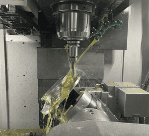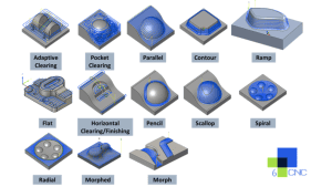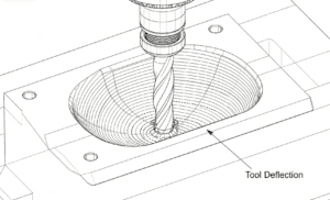
![Comparison of Operating Principles: This figure illustrates a microscopic comparison of the surface waviness and residual scallop height generated by a face milling cutter and a ball-nose cutter under different stepover and step-down settings. [Figure 4-1]](https://6-cnc.com/wp-content/uploads/2026/06/image-2.png)
Face milling and peripheral milling can both create flat surfaces, but they load the cutter differently and leave different surface patterns. Selecting between them affects tool access, material removal, edge quality and how the finished face relates to the part datums.
The choice is rarely based on the process name alone. It depends on whether the job is to produce a broad reference face, size a side wall, create a shoulder or finish a narrow edge.
How the cutting directions differ
In face milling, the spindle axis is generally perpendicular to the machined plane. Multiple inserts or cutting edges sweep across the top surface. This makes the process effective for establishing broad flat faces and preparing datum surfaces.
In peripheral milling, the spindle axis is parallel to the generated surface and the cutter circumference performs most of the cutting. End mills and side cutters use this action to machine vertical walls, shoulders and edges.
An end mill may perform both actions in one toolpath. The useful distinction is where the primary cutting load occurs and which surface the operation is intended to control.
Surface finish and flatness
Face-milled surfaces show a pattern influenced by insert geometry, cutter runout, feed per tooth and the relationship between cutter diameter and workpiece width. Wiper inserts or a controlled finishing pass can improve the result, but a finer visual pattern does not automatically prove better flatness.
Peripheral finish depends strongly on tool deflection, flute condition and axial depth. A long end mill can leave mismatch lines or taper on a tall wall. If the wall controls assembly, inspection should check orientation and location relative to the datum, not roughness alone.
For both methods, clamping and residual stress can cause a nominally flat surface to move after material is removed or the part is released.
Tool and setup considerations
A face mill can cover a broad area efficiently, but the cutter and holder need lateral clearance beyond the workpiece edges. Interrupted surfaces, clamps and raised features may limit the path. End mills provide better access around local features but may require more passes over a large face.
Peripheral cutting can generate radial force that pushes a wall or slender tool sideways. Face milling often creates a stronger axial force component into the setup. The fixture should support the direction of the dominant load.
Material also matters. Insert grade, edge preparation and chip space should match aluminum, steel, stainless steel or plastic rather than treating one cutter as universal.
How to select the operation
Use face milling when the main objective is a broad top surface, stock preparation or a stable datum. Use peripheral milling when controlling an outside profile, shoulder, vertical wall or narrow side surface.
Some parts require both. A plate may be face milled to establish thickness and flat reference surfaces, then peripheral milled to control the outer profile relative to those datums. Planning the sequence is as important as selecting the cutter.
Face milling and peripheral milling comparison
| Factor | Face milling | Peripheral milling |
|---|---|---|
| Tool-axis relationship | Perpendicular to the main surface | Parallel to the main surface |
| Typical feature | Broad flat face | Side wall, shoulder or profile |
| Primary cutting edges | Face and peripheral edges | Cutter circumference |
| Common force concern | Axial load into the setup | Radial deflection of tool or wall |
| Access need | Clear sweep over the face | Clearance beside the profile |
| Common quality risk | Insert runout or surface mismatch | Wall taper or chatter |
Compare the geometry using ap, ae and entering angle
In both operations, axial depth of cut ap measures engagement along the tool axis and radial width ae measures engagement across cutter diameter. Their practical meaning changes with the feature. Face milling usually uses a shallow ap and a broad ae across a top surface. Peripheral shoulder milling may use a larger axial engagement along a wall with a smaller radial step.
Entering angle changes how cutting force divides into axial and radial components and changes chip thickness for a given feed per tooth. A 90-degree shoulder cutter directs more force radially than a lower entering-angle face mill. That matters when the workpiece is thin, the setup is flexible or the spindle has limited stability.
Worked example: establish a datum, then machine a wall
Consider a rectangular automation plate with a bottom mounting face and two side rails. Operation one face mills the mounting surface to establish datum A. The broad cut is efficient and provides a reference for thickness. After the part is located on datum A, peripheral milling controls rail walls relative to that face.
If the drawing only specifies Ra on both surfaces, it misses the functional relationships. The mounting surface may require flatness; the rail may require perpendicularity to datum A and profile relative to locating holes. Roughness describes small-scale texture, not overall form or orientation.
Face-milling cutter diameter affects engagement symmetry
A face cutter must be selected with the workpiece width, spindle power, machine travel and clamp clearance in mind. A cutter path that is strongly off-center changes how each insert enters and exits the workpiece. That changes impact, chip formation and the direction of the resulting cutting forces.
One-pass coverage can reduce cycle time, but a very large cutter adds rotating mass, power demand and clearance requirements. A smaller cutter needs overlapping passes and may leave witness lines if insert height, runout or toolpath spacing is not controlled. The lowest-risk choice balances coverage with machine and setup capability.
Peripheral milling is controlled by tool deflection
For a tall wall, the cutting edge may engage over a large axial length. Radial cutting force bends the tool away from the wall, often producing taper. A spring pass may remove additional material, but relying on repeated spring passes is not a substitute for rigid tooling and predictable stock.
Strategies include reducing radial engagement, using a shorter or larger-diameter tool, dividing axial depth, leaving uniform finish stock and alternating passes to balance a thin wall. The correct combination depends on material and wall support.
Use the correct surface metric
Ra is an arithmetic average of profile deviations and can hide isolated peaks or periodic waviness. Rz responds differently to peak-to-valley behavior. Neither value alone proves flatness, perpendicularity or sealing performance. For a gasket face, the lay direction and absence of a continuous leak path may matter. For a sliding wall, waviness and orientation can influence contact.
Specify the metric that links to function, then agree on cutoff, sampling direction and instrument when the requirement is critical. Avoid copying the same roughness value onto every machined face.
Estimate productive output without ignoring stability
Material removal rate follows Q = ap × ae × Vf. This makes it tempting to maximize each term, but machine power, torque, insert load, workholding and chip evacuation set the safe window. Sandvik’s selection guidance emphasizes machine stability, power, spindle size, clamping and the shortest possible overhang before choosing a milling concept.
For a real quote, compare total operation time: loading, probing, roughing, tool changes, finishing and inspection. A specialized face mill may remove a broad surface quickly, while a versatile shoulder mill may reduce tool changes on low-volume mixed work. Production volume determines which advantage matters more.
Technical references
What to send with your RFQ
- Identify the functional face or wall
- Define its relationship to part datums
- Separate roughness from flatness and orientation
- Check cutter and holder clearance
- Support the dominant cutting-force direction
- Plan roughing, stress release and finishing order
- Choose an inspection method for the controlled feature
A useful RFQ gives the manufacturing team enough information to separate functional requirements from preferences. If a feature is difficult to reach or inspect, a short engineering review before release can prevent a costly revision later.
Review the part before production
Send 6CNC your CAD model, drawing, material and quantity. Our team will review machining access, setups, critical tolerances and inspection needs before quoting.
Frequently asked questions
Is face milling the same as end milling?
No. End milling describes operations performed with an end mill, which may use both its end and peripheral cutting edges. Face milling typically uses a wider cutter primarily for broad faces.
Which process gives a better surface finish?
Either can produce a controlled finish. The result depends on tool geometry, runout, rigidity, cutting parameters and whether the surface is a face or wall.
Can peripheral milling make a flat surface?
Yes. It commonly creates flat side walls and shoulders parallel to the tool axis.
Why use both processes on one part?
Face milling can establish reference planes, while peripheral milling then locates side features and profiles relative to those datums.
Plan the process around the functional features
Good CNC machining starts with a clear definition of what the part must do. Tool access, rigidity, datums and inspection should support that function. For additional process options, see our CNC milling services, 5-axis machining and quality assurance resources.