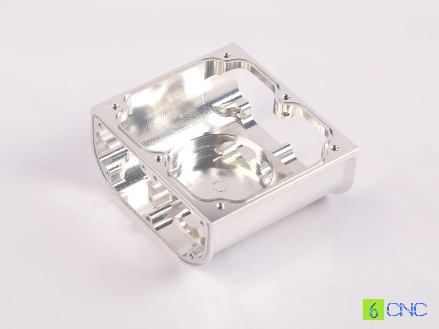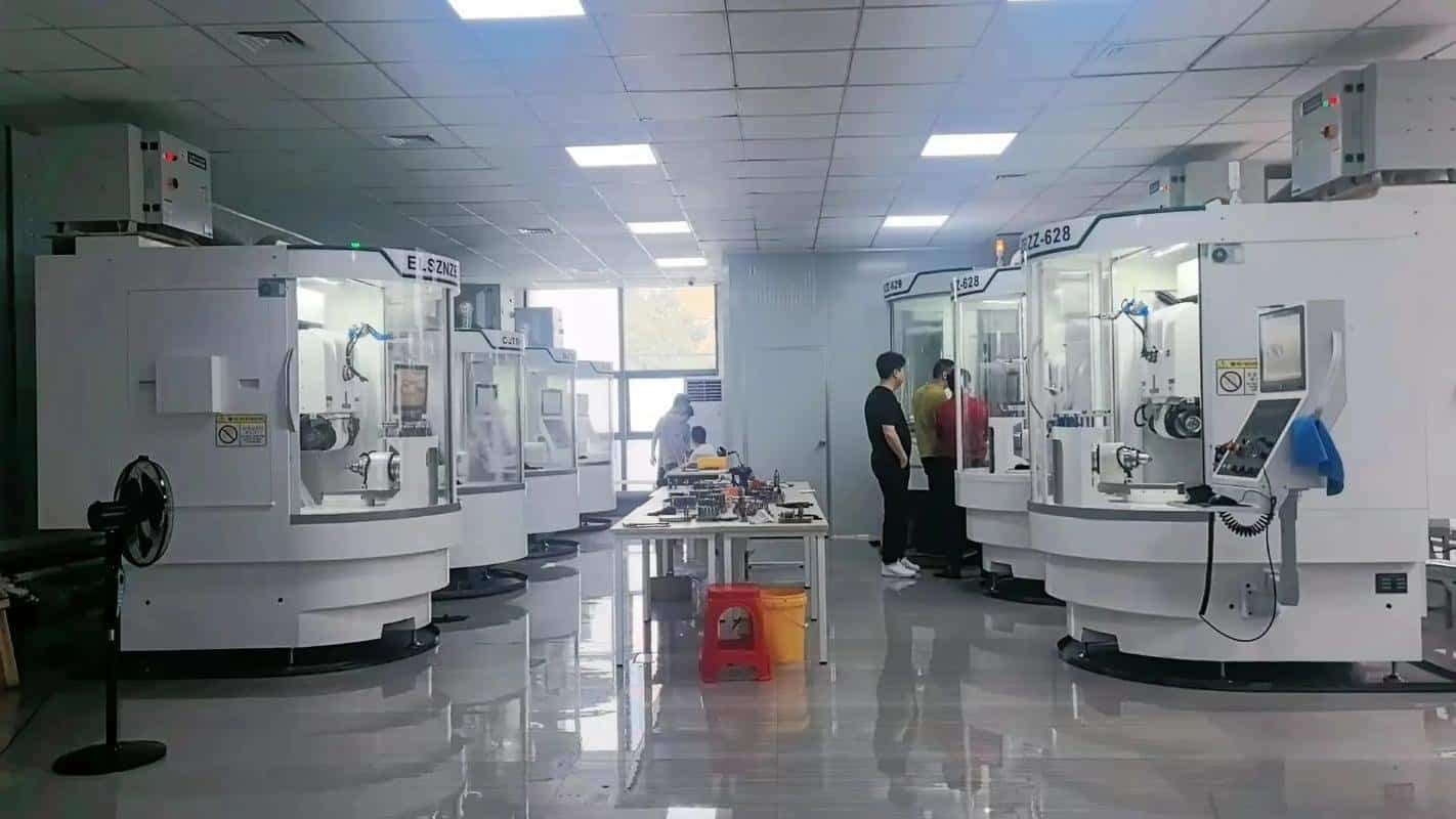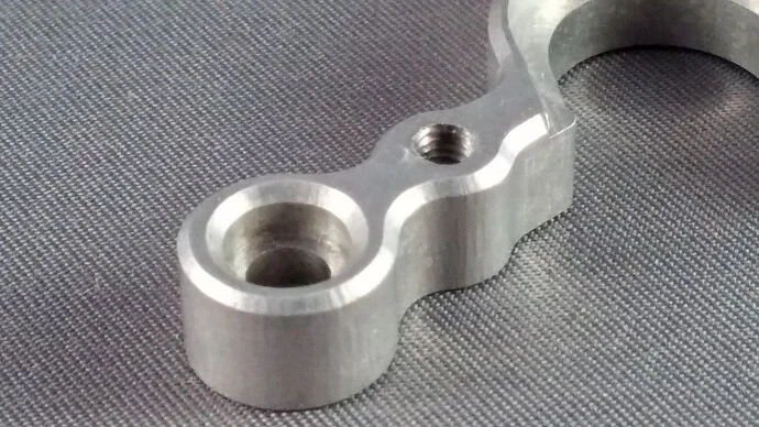
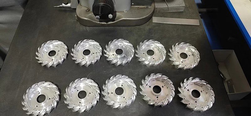
Owning CNC equipment gives an engineering team enormous flexibility.
You can make fixtures internally, modify prototypes without waiting for an outside supplier, produce replacement components quickly, and keep sensitive development work under your own roof.
But there is an important difference between having a CNC machine capable of cutting a feature and having a machining process capable of producing that feature repeatedly, within tolerance, with acceptable surface quality.
That difference becomes obvious when the parts get harder.
A component may require five-axis access, several closely related datums, thin unsupported walls, deep internal features, difficult materials, tight geometric tolerances, or dimensions that must remain stable across an entire small production batch.
At that point, the question is no longer:
“Can our machine remove this material?”
The better question is:
“Can our complete process manufacture this part reliably?”
Here are ten complex machining tasks that commonly expose the limits of an in-house CNC setup—and the engineering factors to consider before deciding whether to machine the part internally or send it to a specialized CNC supplier.
When Does a CNC Part Become “Too Complex” for an In-House Setup?
Machine complexity is not determined by the number of features on a drawing.
A component with 50 relatively forgiving holes may be easier to manufacture than a simple-looking housing containing two bearing bores with strict position, cylindricity, and coaxiality requirements.
The real difficulty usually comes from several variables interacting at once:
| Machining challenge | What makes it difficult |
|---|---|
| Tight tolerances | Tool wear, thermal growth, machine accuracy and inspection |
| Complex geometry | Tool access, collision avoidance and multiple orientations |
| Thin walls | Deflection, vibration and residual stress |
| Deep cavities | Tool overhang, chip evacuation and chatter |
| Difficult materials | Heat, cutting forces and accelerated tool wear |
| Multiple critical datums | Setup-to-setup error accumulation |
| Fine surface requirements | Toolpath, cutting stability and secondary finishing |
| Small precision features | Runout, tool breakage and measurement limitations |
| Large precision parts | Machine travel, rigidity and thermal stability |
| Repeat small-batch production | Process control and repeatability |
The machine tool is therefore only one part of the capability.
CAM programming, cutting tools, workholding, probing, inspection equipment, operator experience and process control can be equally important.
1. Five-Axis Parts With Features on Multiple Faces
A three-axis machining center can produce extremely sophisticated components.
The problem begins when important features point in several directions.
Consider a robotic wrist housing with:
- angled mounting holes;
- intersecting bores;
- curved exterior surfaces;
- internal pockets;
- bearing seats on different axes;
- connector openings on several sides.
A 3-axis machine may technically manufacture the component, but doing so could require five, six or even more individual setups.
Every time the part is repositioned, another source of error enters the process.
Datum transfer becomes more difficult. Fixtures must locate the part accurately. Previously machined surfaces may become clamping surfaces. Small setup errors can accumulate until relationships between features no longer satisfy the drawing.
Why five-axis machining changes the equation
A 5-axis machining center can orient the workpiece relative to the cutting tool without repeatedly removing the component from the fixture.
Depending on the geometry, this can provide:
- access to multiple faces in one setup;
- shorter cutting tools;
- improved tool rigidity;
- fewer datum transfers;
- better positional relationships between features;
- easier machining of compound angles and contoured surfaces.
Five-axis machining does not automatically make a component accurate.
Good fixturing, machine calibration, CAM programming and inspection are still required.
But when multiple critical features must maintain accurate relationships across different orientations, reducing the number of setups can significantly simplify the process.
Parts that commonly benefit
Typical examples include:
- aerospace structural components;
- medical instrument bodies;
- robotic joints;
- optical mounts;
- impellers;
- turbine-related components;
- complex manifolds;
- semiconductor equipment components.
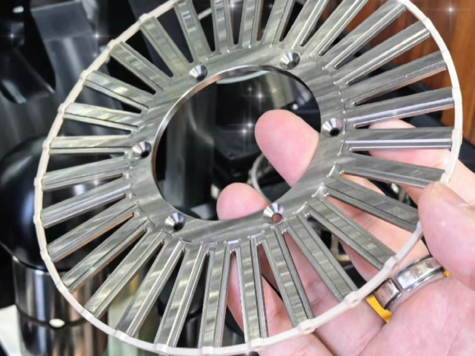
If your in-house process requires a complicated sequence of custom fixtures simply to expose every machined face, five-axis outsourcing may be worth evaluating.
2. Parts With Several Interdependent Tight Tolerances
A ±0.01 mm dimension is not automatically difficult.
What makes precision machining challenging is having many critical dimensions that interact with one another.
Imagine an aluminum housing containing two bearing bores.
The drawing may control:
- bore diameter;
- bore roundness;
- center distance;
- coaxiality;
- perpendicularity to a mounting face;
- position relative to locating pins.
Individually, none of these requirements necessarily looks extraordinary.
Together, they create a much more demanding manufacturing problem.
The machinist must control not only the size of each feature but the geometric relationship between those features.
Where accuracy can disappear
Several factors influence the finished part:
Machine condition
Backlash, spindle condition, axis positioning and machine geometry matter increasingly as tolerances become tighter.
Thermal variation
Machines, cutting tools and workpieces all change dimension as temperature changes.
Tool condition
A worn cutter may continue producing apparently acceptable surfaces while dimensions slowly drift.
Workholding
An accurately machined feature can move after the clamps are released if the part was distorted during machining.
Measurement
There is little value in specifying a tolerance that the inspection process cannot reliably verify.
For complex precision parts, process planning often becomes more important than simply selecting a highly accurate CNC machine.
A capable supplier may establish critical dimensions as process-control points during machining rather than waiting until final inspection to discover that the process has drifted.
3. Thin-Wall Components That Distort After Machining
Thin-wall machining is one of the best examples of a part that appears simple in CAD but behaves very differently on the machine.
Typical components include:
- electronics enclosures;
- aerospace housings;
- battery components;
- instrument shells;
- lightweight robotic structures;
- optical equipment housings.
As material is removed, the workpiece becomes less rigid.
Cutting forces that would barely affect a solid block can deflect a thin wall enough to change the finished dimension.
Clamping introduces another problem.
Clamp the component too loosely and it can move.
Clamp it too tightly and the walls may distort during machining, only to spring back when the fixture is released.
Residual stress inside the raw material can also cause a component to move as large volumes of material are removed.
Thin-wall machining often requires a strategy, not just a lighter cut
Possible approaches include:
- balanced roughing;
- leaving temporary support material;
- staged material removal;
- low-force finishing passes;
- specialized soft jaws;
- sacrificial supports;
- vacuum workholding where appropriate;
- controlling tool engagement;
- allowing stress-relief stages before finishing critical dimensions.
The exact method depends on material, wall geometry and tolerance requirements.
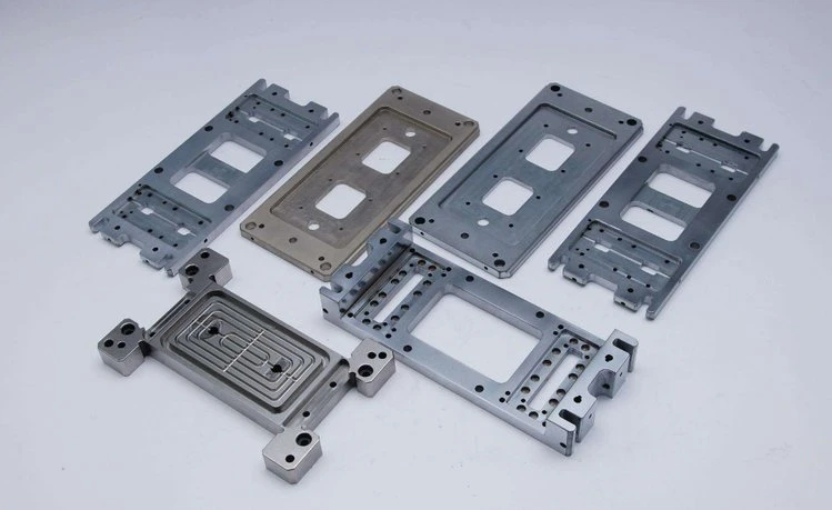
This is why changing a CAD wall from 2 mm to 0.8 mm can have a much larger manufacturing consequence than the designer might expect.
4. Deep Cavities, Deep Pockets and High Aspect-Ratio Features
Deep pockets create a fundamental CNC problem:
the tool must reach the cutting area without the toolholder colliding with the surrounding geometry.
That usually means increasing cutter length.
Unfortunately, increasing tool overhang reduces rigidity.
The result may be:
- chatter;
- tool deflection;
- tapered walls;
- poor corner accuracy;
- poor surface finish;
- accelerated tool wear;
- broken cutters.
Chip evacuation becomes increasingly important as the cavity gets deeper.
If chips remain inside the pocket, the cutter can recut them repeatedly, increasing heat and damaging the surface.
Coolant also becomes more difficult to deliver effectively to the cutting zone.
Geometry can make the situation worse
A deep rectangular pocket with large internal radii may be manageable.
A deep cavity containing:
- narrow channels;
- small corner radii;
- ribs;
- varying floor depths;
- undercuts;
- intersecting features
can require an entirely different machining strategy.
Sometimes the better solution is not a more aggressive cutter.
It may involve:
- machining from another orientation;
- using five-axis access;
- changing corner radii;
- splitting the manufacturing process;
- using EDM for inaccessible features.
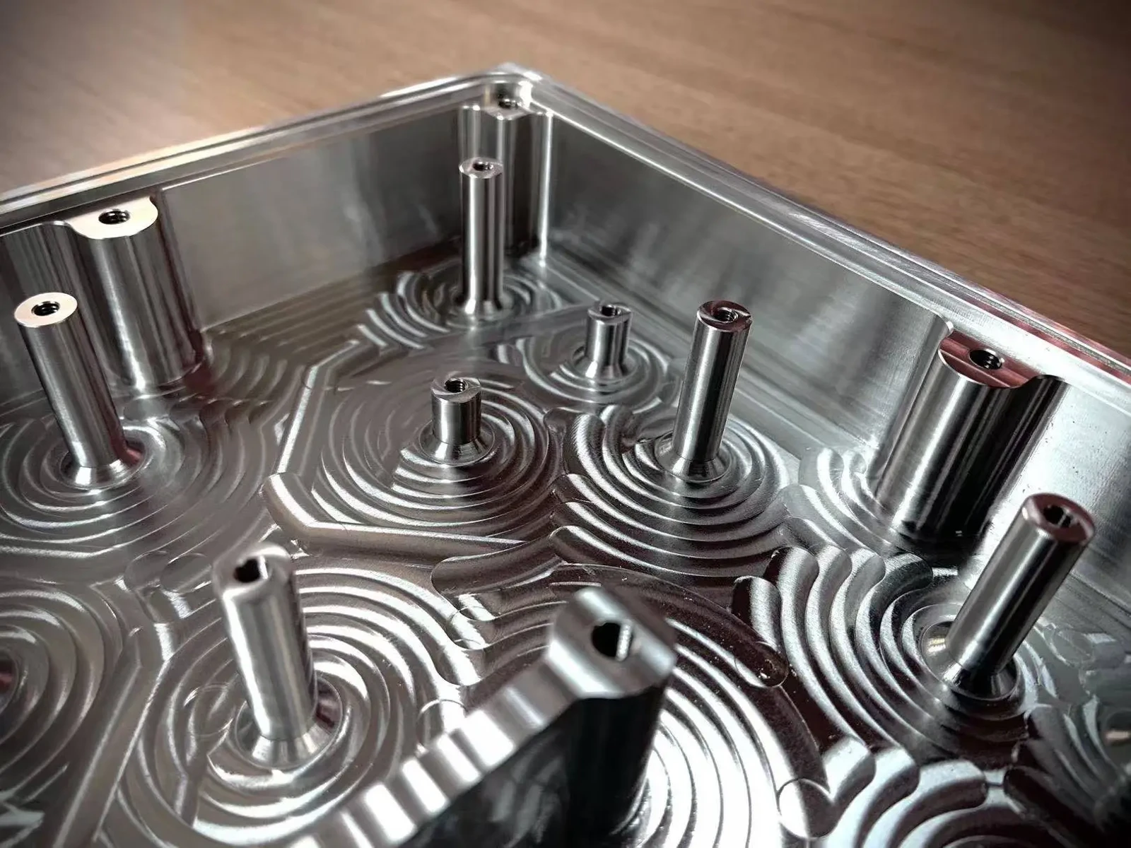
A machining supplier that reviews these features before production can often identify relatively small design changes that dramatically improve manufacturability.
5. Titanium, Inconel and Other Difficult-to-Machine Materials
A toolpath that works beautifully in 6061 aluminum cannot simply be transferred to titanium by reducing the feed rate.
Materials behave differently under the cutting edge.
Titanium alloys, nickel-based superalloys, hardened steels and other demanding materials can introduce combinations of:
- high cutting temperatures;
- concentrated heat at the cutting edge;
- rapid tool wear;
- high cutting forces;
- work hardening;
- difficult chip control.
The challenge becomes greater when difficult materials are combined with deep pockets, thin walls or tight tolerances.
Titanium is a good example
Ti-6Al-4V is widely used because of its excellent strength-to-weight ratio, corrosion resistance and engineering performance.
But machining it requires careful management of tool engagement, cutting temperature and tool condition.
A process that creates excessive heat can shorten cutting-tool life rapidly.
Long tool overhang can introduce vibration.
Aggressive parameters may produce dimensional or surface problems.
For occasional in-house jobs, this may mean spending substantial machine time establishing a stable process.
A shop that machines these materials regularly already has established experience with tooling, feeds and speeds, workholding, coolant strategy and inspection.
That difference becomes particularly important when expensive raw material means one scrapped component costs far more than a normal aluminum prototype.
6. Parts Requiring Milling, Turning and Secondary Precision Operations
Some components do not belong neatly in either the “milled part” or “turned part” category.
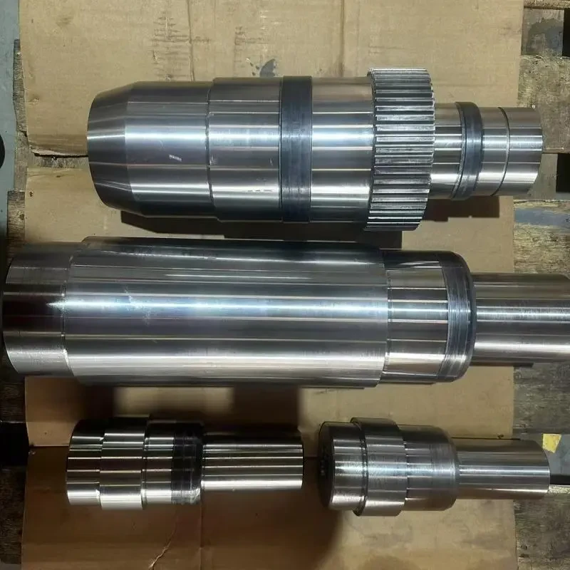
Consider a precision shaft with:
- turned bearing journals;
- milled wrench flats;
- radial holes;
- an off-axis slot;
- precision threads;
- a ground sealing diameter.
Manufacturing the part may require several processes.
A conventional workflow might involve:
- CNC turning;
- transferring the component to a milling machine;
- machining cross-features;
- heat treatment;
- cylindrical grinding;
- final inspection.
Every transfer creates another planning and alignment requirement.
Mill-turn can consolidate operations
Mill-turn machines combine turning and powered-tool milling capabilities within one platform.
For suitable parts, this can reduce the number of separate setups and improve relationships between rotational and milled features.
But some dimensions may still require a specialized finishing process.
Precision grinding may be more appropriate for:
- bearing journals;
- hardened shafts;
- sealing surfaces;
- extremely controlled roundness;
- fine surface-finish requirements.
The important point is not that one manufacturing technology is always superior.
Complex machining often requires choosing the right combination of processes.
That process chain can be difficult to reproduce economically inside a company whose machining department is primarily designed for engineering support or routine components.
7. Precision Features That Are Difficult to Reach With Conventional Cutting Tools
Not every geometry can be produced efficiently with a rotating cutter.
Consider a hardened steel component containing:
- a narrow internal slot;
- a sharp internal corner;
- a deep keyway;
- a small inaccessible cavity.
Conventional milling cutters are circular.
They therefore leave an internal radius.
If the functional design requires geometry that cannot accommodate that radius, reducing cutter diameter only works up to a point.
Eventually the cutting tool becomes too weak, too long or simply unable to access the feature.
This is where complementary processes matter
Wire EDM and sinker EDM can solve geometries that are difficult or impractical to manufacture with traditional milling.
Grinding can achieve conditions that are difficult to obtain through milling or turning alone.
A complex component may therefore use CNC machining for most of the geometry while another process creates only one critical feature.
This matters when comparing suppliers.
A machine shop should not force every feature onto a CNC mill merely because CNC milling is the equipment it happens to have available.
The manufacturing process should follow the geometry.
8. Small Features, Micro Holes and Delicate Details
As features become smaller, normal sources of machining error become proportionally much larger.
Tool runout that is insignificant for a 10 mm end mill can become critical when the cutting tool itself is extremely small.
Micro-sized tools also have very little tolerance for:
- incorrect feeds;
- vibration;
- chip packing;
- spindle runout;
- poor toolholding;
- accidental contact.
The cutter may fail before an operator can visually recognize the problem.
Inspection becomes another challenge
Manufacturing a tiny feature is only half the job.
You must also be able to determine whether it is correct.
Depending on the feature, inspection might require:
- optical measurement;
- microscopy;
- precision pins;
- specialized gauges;
- high-resolution dimensional measurement.
This becomes increasingly relevant for components used in:
- medical devices;
- miniature robotics;
- electronics;
- optical systems;
- semiconductor equipment;
- precision instrumentation.
When small features are critical to the component’s function, both machining capability and measurement capability should be reviewed before production begins.
9. Large Components That Still Require Precision Relationships
Large parts create a different kind of CNC problem.
The first limitation is obvious: machine travel.
The part simply has to fit.
But fitting inside the work envelope does not automatically mean the machining process is suitable.
Large components can introduce:
- long machining cycles;
- difficult lifting and setup;
- large fixture requirements;
- thermal variation;
- tool reach problems;
- vibration;
- large quantities of removed material.
Now add precision.
For example, consider a large automation plate containing locating holes and mounting features distributed across a wide area.
Holding a reasonable tolerance on one hole may not be difficult.
Maintaining accurate positional relationships across the entire plate is a different challenge.
Similarly, machining a long shaft requires considering support, deflection and runout—not simply whether the turning center accepts the overall length.
Large precision machining therefore requires matching part size, machine capacity, rigidity, workholding and inspection capability rather than checking only the nominal machine envelope.
10. Small-Batch Production Where Every Part Must Match the First Article
Making one good component proves that the geometry can be manufactured.
It does not necessarily prove that the process is stable.
The distinction becomes important when a prototype develops into a batch of:
- 20 parts;
- 50 parts;
- 100 parts;
- 300 parts;
- 600 parts.
Now the challenge becomes repeatability.
Tool wear develops throughout the batch.
Material lots may behave differently.
Fixtures must repeatedly locate parts.
Offsets may require controlled adjustment.
Critical dimensions need to remain within the allowable process window.
Small-batch manufacturing has its own engineering problem
High-volume factories can justify expensive dedicated automation and hard tooling.
Prototype shops can spend considerable attention on one component.
Small-batch precision production sits between those extremes.
The process has to be repeatable enough for production while remaining flexible enough that expensive dedicated tooling does not overwhelm the economics of the project.
For this reason, small batches often benefit from:
- reusable or modular fixturing;
- probing;
- controlled tool-life strategies;
- documented inspection stages;
- first article verification;
- in-process checks on critical dimensions;
- final dimensional inspection.
This is especially important when the components will enter an assembly.
A batch in which every individual part technically passes inspection can still cause problems if dimensional variation makes assembly inconsistent.
The Machine Is Only One Part of the Machining System
One of the most common mistakes in CNC sourcing is comparing machine lists.
A supplier owns a five-axis machining center, therefore it must be capable of making a difficult five-axis component.
Not necessarily.
A complete precision machining system includes:
CAM and process planning
Someone must decide:
- machining sequence;
- datum strategy;
- cutting-tool access;
- roughing method;
- finishing strategy;
- fixture concept;
- inspection sequence.
Workholding
The fixture must hold the component securely without introducing unacceptable deformation.
Cutting tools
Tool geometry, coating, holder selection and overhang influence the real machining result.
Machine capability
Machine rigidity, spindle characteristics, axis configuration and control performance determine what process strategies are practical.
Measurement
Calipers and micrometers are useful, but they cannot verify every geometric relationship appearing on a complex engineering drawing.
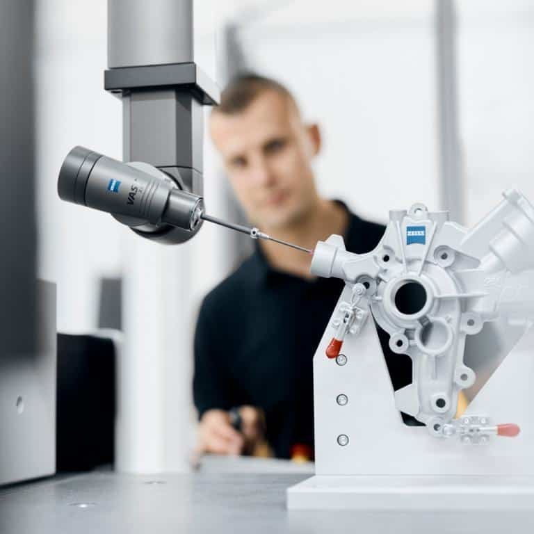
Depending on the component, inspection may involve CMM measurement, optical measurement, gauges, surface roughness testing or other systems.
Process control
The manufacturing team also needs a method for responding when tools wear or dimensions begin moving toward tolerance limits.
A sophisticated CNC machine cannot compensate for a weak process surrounding it.
Should You Machine the Part In-House or Outsource It?
There is no reason to outsource a component simply because it looks difficult.
If your team has the right equipment and experience, manufacturing internally may provide excellent speed and control.
Instead, evaluate the project against the actual constraints.
Keep it in-house when:
Your existing equipment comfortably accommodates the geometry, tolerance and material.
The necessary inspection tools are available.
Your team already understands the machining process.
Required fixtures are straightforward.
Machine capacity is available without disrupting higher-priority operations.
The component will undergo frequent engineering changes and immediate iteration is valuable.
Consider outsourcing when:
The part requires equipment that you rarely use.
Five-axis machining would eliminate numerous setups.
Complex GD&T relationships are difficult to inspect internally.
Thin walls or delicate geometry have produced repeated scrap.
The material requires specialized tooling and machining knowledge.
Secondary processes complicate internal coordination.
Your machines can technically make the part but would remain occupied for an unreasonable amount of time.
You need repeatable small-batch production rather than a single successful prototype.
The most useful comparison is usually not:
Internal machining cost vs. supplier price.
It is:
Total internal manufacturing risk and resource consumption vs. outsourced manufacturing cost.
That includes programming, setup, tooling, scrap, inspection, machine occupancy and engineering time.
A Practical Checklist Before Sending a Complex CNC Part for Quotation
A machining supplier can give a much more useful response when the engineering requirements are clear.
Before requesting a quote, provide:
3D CAD model
STEP is commonly useful for machining review.
Engineering drawing
Include critical dimensions, tolerances, GD&T and surface requirements that cannot be inferred reliably from the CAD model.
Material
Specify the exact alloy or polymer grade where material properties matter.
Quantity
Prototype quantity and production quantity can lead to very different manufacturing strategies.
Surface finish
Identify functional surfaces separately from cosmetic requirements.
Post-processing
Include anodizing, heat treatment, plating, passivation, grinding or other requirements.
Inspection requirements
Identify the characteristics that require dimensional reports or specific verification.
Most importantly, identify which dimensions actually control part function.
Treating every dimension as equally critical usually increases machining and inspection cost without improving the finished product.
How 6CNC Approaches Complex Small-Batch Machining
At 6CNC, complex machining projects are reviewed as manufacturing processes rather than simply as CAD files that need toolpaths.
Our focus is prototype through small-batch precision manufacturing, particularly when projects require a combination of complex geometry, controlled tolerances and repeatable production.
Depending on the part, the manufacturing route may involve:
- CNC milling;
- CNC turning;
- 5-axis machining;
- mill-turn machining;
- cylindrical grinding;
- surface grinding;
- centerless grinding;
- Wire EDM;
- additional finishing and manufacturing processes.
For dimensional verification, our quality workflow can incorporate CMM, 2D measurement systems, gauges, micrometers, calipers, surface roughness measurement and material verification equipment depending on project requirements.
Critical dimensions can be reviewed during production rather than relying exclusively on final inspection.
That matters when moving from the first successful component into repeat small-batch production.
Complex Machining Is Usually a Process Problem
The hardest CNC components are rarely difficult because of one dramatic feature.
Complexity normally comes from combinations:
A titanium component that is also thin-walled.
A housing that needs five-axis access and tightly related bearing bores.
A shaft combining turning, milling, heat treatment and grinding.
A deep cavity that also contains small corner radii.
A large component with precision positional requirements.
Or a prototype that now needs to become 200 repeatable production parts.
In those situations, adding another cutter or another setup does not always solve the underlying manufacturing problem.
The entire process has to work together:
machine + tooling + fixture + programming + measurement + process control.
If your internal CNC department is already equipped for that process, keeping the work in-house makes sense.
If not, outsourcing the difficult portion can allow your engineering team to keep the speed and flexibility of internal machining without forcing every part through equipment that was never intended for the job.
Frequently Asked Questions
What makes a CNC machining job complex?
CNC complexity usually results from interactions between geometry, tolerance, material, tool access, workholding and inspection. A part does not need to look complicated to be difficult. A simple housing containing several tightly related precision bores may be more challenging than a visually complex component with generous tolerances.
When should a company outsource CNC machining?
Outsourcing is worth considering when a project requires equipment, inspection capability or specialized process knowledge that is rarely used internally. It can also make sense when manufacturing the component internally would occupy valuable machine capacity or require excessive tooling and setup development.
Is 5-axis CNC always better than 3-axis machining?
No. Simple components are often more economically manufactured on 3-axis machines. Five-axis machining becomes particularly valuable when parts contain features on several orientations, compound angles, deep geometries or surfaces that would otherwise require numerous setups.
Why are thin-wall CNC parts difficult to machine?
Thin sections have limited rigidity and can deflect under cutting or clamping forces. Material removal may also release residual stresses and change the final geometry. Machining sequence, support, cutting forces and workholding therefore become particularly important.
Why are titanium and Inconel difficult to machine?
These materials can generate high cutting temperatures and demanding cutting conditions while accelerating tool wear. Stable tooling, appropriate cutting parameters, coolant management and controlled tool engagement are therefore especially important.
Can a CNC supplier guarantee every tight tolerance shown on a drawing?
Tolerance capability depends on the feature, material, geometry, part size, process and inspection method. Important tolerances should be reviewed individually rather than assuming a single tolerance value applies equally to every feature.
What information should I provide when requesting a quote for a complex CNC part?
Provide the 3D CAD file, engineering drawing, material specification, quantity, surface requirements, post-processing requirements and any special inspection requirements. Clearly identifying function-critical dimensions helps the supplier develop an appropriate manufacturing and inspection plan.
Can 6CNC handle prototypes and small-batch production?
Yes. 6CNC focuses on custom precision machining from prototypes into small-batch manufacturing. Projects can be reviewed for machining strategy, workholding, critical dimensions and inspection requirements before production begins.
Need Help With a Difficult CNC Part?
If your component involves complex geometry, tight tolerances, difficult materials or prototype-to-small-batch production, send 6CNC your CAD files and engineering drawings.
Our engineering team can review the geometry, material, tolerances and expected quantity to determine a practical machining route before production begins.