Choosing between 3-axis and 5-axis CNC machining is not simply a question of which machine is more advanced.
A 5-axis machining center can approach a part from more directions, reduce repositioning, and machine complex surfaces that would be difficult or impossible on a conventional 3-axis setup. But that does not automatically make it the better choice for every component. For a simple aluminum plate, bracket, or open housing, 3-axis machining may produce the required accuracy faster and at a lower cost.
The real decision depends on the geometry of the part, how many orientations are needed, whether critical features must remain related across different faces, how deeply the cutting tool needs to reach, and how much setup time and process risk each machining strategy creates.
A useful way to think about the difference is this:
3-axis machining asks whether every feature can be reached through practical setups.
5-axis machining asks whether changing the tool orientation can make those setups simpler, more rigid, or more accurate.
This guide compares 3-axis and 5-axis CNC machining from a manufacturing perspective, including machine motion, part complexity, setup strategy, accuracy, surface finish, tooling, cycle time, cost, and the types of parts that benefit most from each process.
What Is 3-Axis CNC Machining?
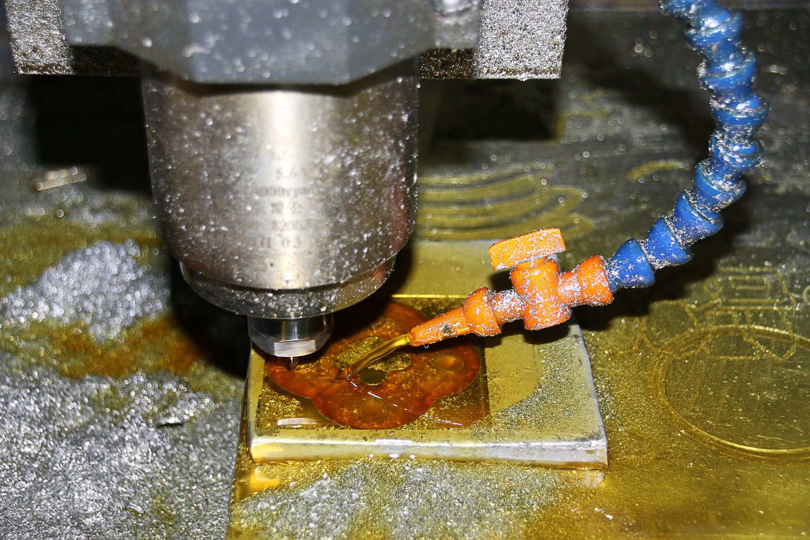
A 3-axis CNC milling machine moves the cutting tool along three linear directions: X, Y, and Z. The workpiece is typically fixed in one orientation while the cutter approaches from the spindle direction.
The three axes control:
- X-axis: left-to-right movement;
- Y-axis: front-to-back movement;
- Z-axis: up-and-down movement.
This configuration is capable of far more than simple flat machining. Modern 3-axis machining centers can produce pockets, slots, drilled holes, threaded holes, contoured surfaces, complex 3D cavities, and precision bores as long as those features remain accessible from the selected orientation.
Typical 3-axis parts include:
- mounting plates;
- machine brackets;
- electronics housings;
- fixtures;
- mold inserts;
- valve blocks;
- heat sinks;
- structural components;
- simple medical-device housings;
- optical equipment plates.
A common misconception is that 3-axis machines are only suitable for simple components. In reality, highly complex parts can be produced on 3-axis equipment. The limitation is usually not geometric complexity alone—it is tool access and the number of setups required to reach that geometry.
What Is 5-Axis CNC Machining?
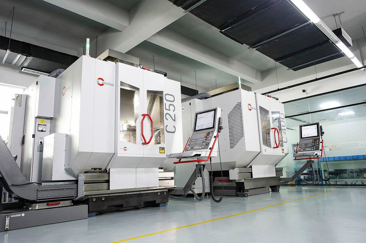
A 5-axis CNC machine combines the three linear X, Y, and Z axes with two rotational axes. Depending on machine architecture, the table may tilt and rotate, the spindle head may move, or both may contribute to the rotary motion.
These additional axes allow the cutting tool to approach the workpiece from multiple directions.
This is particularly useful when a part contains:
- features on several faces;
- compound-angle holes;
- deep cavities;
- tilted surfaces;
- impeller blades;
- turbine geometry;
- sculpted aerospace surfaces;
- complex medical components;
- optical housings with multi-directional interfaces.
The key advantage is not simply that the machine can “move in five axes.”
It is that tool orientation can become part of the machining strategy.
Instead of forcing the cutter to remain vertical while reaching deep into a component, the machine can tilt the tool or workpiece into a more favorable direction. This can improve access, reduce tool length, decrease vibration, and keep several related features inside one setup.
3+2 Machining and Simultaneous 5-Axis Machining Are Not the Same
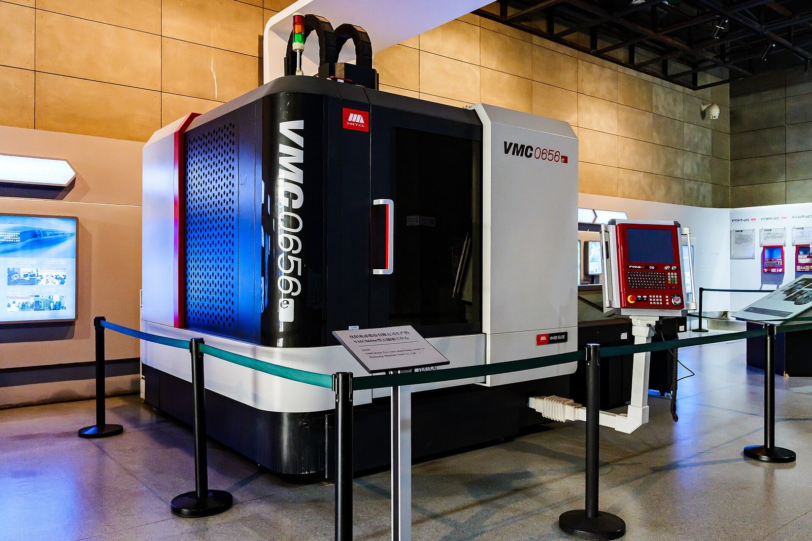
One of the most important distinctions is often missing from basic 3-axis vs 5-axis comparisons.
Not all 5-axis machining involves all five axes moving at the same time.
3+2 Positional Machining
In 3+2 machining, the rotary axes first position the part at a specific angle. Once that position is reached, the rotary axes remain fixed and the machine performs conventional 3-axis cutting.
For example, a housing may need machining on the top face and on two angled side faces. Instead of removing the part and placing it in three different fixtures, a 5-axis machine can rotate the workpiece into each position while keeping the original datum and setup.
This is extremely useful for:
- multi-face housings;
- angled holes;
- brackets;
- valve bodies;
- fixtures;
- prismatic parts with features on several orientations.
Simultaneous 5-Axis Machining
In simultaneous 5-axis machining, the linear and rotary axes move together during the cut.
The tool orientation changes continuously while following the surface.
This is required for parts such as:
- impellers;
- turbine blades;
- blisks;
- strongly twisted surfaces;
- complex aerospace components;
- some medical implants;
- freeform optical or mold surfaces.
A turbine blade, for example, may change curvature and orientation continuously from root to tip. A fixed-angle cutter cannot follow the complete geometry efficiently. Simultaneous 5-axis motion allows the tool axis to adapt continuously to the changing surface.
This distinction matters because many parts advertised as “5-axis” do not actually require simultaneous five-axis motion. Sometimes 3+2 machining provides the same practical advantage at lower programming complexity.
The Biggest Difference Is Often Setup Count
A setup is every time the workpiece must be located and held in a particular orientation for machining.
A simple block may require two setups: machine one side, flip the part, then finish the opposite side.
A more complex housing may require four, five, or six orientations.
Each additional setup introduces work:
- Remove the component.
- Clean the workpiece and fixture.
- Reposition the part.
- Locate it against the new datum.
- Clamp it.
- Establish the new work coordinate.
- Verify alignment.
- Continue machining.
If the part contains relatively loose tolerances between faces, this may be completely acceptable.
The problem appears when precision relationships span several setups.
Consider an aluminum robotic joint housing with bearing bores on two perpendicular faces. If those bores must maintain a tight positional relationship, machining each face independently means the fixture and datum transfer become part of the error chain.
A 5-axis process may allow both bores to be machined from the same setup.
This does not make the CNC machine inherently more precise. It simply removes several opportunities for alignment error.
That difference is important.
3-Axis Machining Is Often the Better Choice for Simple Geometry
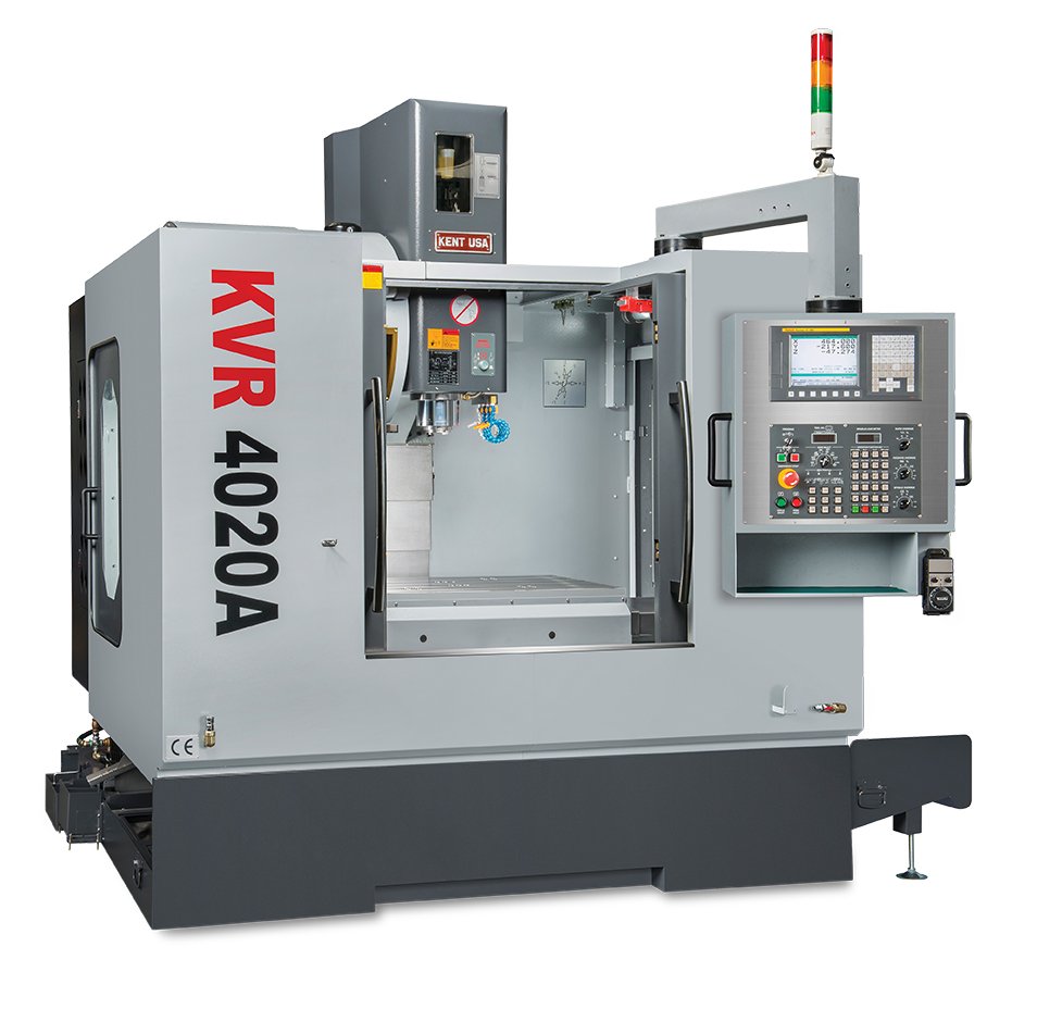
There is little benefit in using an expensive 5-axis machine when the part does not require the additional motion.
Consider a 6061 aluminum mounting plate containing:
- several counterbored holes;
- two pockets;
- threaded holes;
- an external profile.
If all features can be reached from the top and bottom, a 3-axis machining center may complete the component in two straightforward setups.
Using 5-axis equipment may not meaningfully reduce setup time or improve part quality. Instead, the higher hourly machine rate and programming complexity could increase manufacturing cost.
This is why 3-axis machining remains one of the most widely used processes for custom parts.
It is efficient, predictable, and highly capable when geometry allows reasonable access.
When 5-Axis Machining Starts to Make Sense
The value of five-axis machining becomes clearer when the geometry creates access or setup problems.
Features on Multiple Faces
A housing may contain pockets, bores, threaded holes, and connector openings on four or five sides.
On a 3-axis machine, this usually requires several setups or specialized fixtures.
A 5-axis machine can rotate the component while maintaining one primary setup.
This is especially valuable when several features are related by GD&T requirements.
Compound Angles
An angled hole is not necessarily difficult. It can often be produced using a fixture that tilts the workpiece.
The challenge begins when a component contains several holes or surfaces at different compound angles.
Building and verifying separate fixtures may quickly become inefficient.
Five-axis positioning allows those angles to be created directly.
Deep Cavities
Deep cavities often require long cutting tools on 3-axis machines.
As tool overhang increases, rigidity decreases.
This can cause:
- chatter;
- tool deflection;
- tapered walls;
- poor surface finish;
- shortened tool life.
A 5-axis machine may tilt the part toward the cutter so that a shorter tool can reach the same feature.
That can improve machining performance even when the surface itself is not especially complicated.
Undercut-Like Geometry
True undercuts may still require specialized tooling or EDM, but five-axis orientation can reach many features that are inaccessible from a fixed vertical spindle direction.
Freeform Surfaces
Impellers, turbine blades, molds, and aerodynamic components may contain continuously changing surface angles.
These applications are where simultaneous 5-axis machining becomes particularly valuable.
3-Axis vs 5-Axis: Tool Length and Rigidity
Tool length is one of the most practical reasons to use five-axis machining.
Imagine a deep pocket with a wall 70 mm tall.
On a 3-axis machine, the toolholder must remain above the top of the part while the cutter reaches the bottom. This may require a long-reach end mill.
Long tools are less rigid.
Under cutting load, they can bend slightly.
The machine may command the tool to the correct coordinates, but the cutter itself deflects away from the wall.
The result may include:
- wall taper;
- dimensional error;
- chatter marks;
- inconsistent surface finish.
A 5-axis machine can sometimes tilt the workpiece and approach the wall from another direction.
The cutter no longer needs the same amount of overhang.
A shorter tool can then be used, improving both rigidity and cutting performance.
This is one of the reasons five-axis machining can improve quality even when it does not reduce cycle time dramatically.
Accuracy: Is 5-Axis More Accurate Than 3-Axis?
Not automatically.
A high-quality 3-axis machining center with stable tooling, good fixtures, proper thermal control, and an experienced machining team can produce extremely accurate parts.
A poorly planned five-axis process can still produce scrap.
Machining accuracy depends on the entire system:
- machine condition;
- calibration;
- spindle runout;
- cutter condition;
- toolholder quality;
- workholding;
- temperature;
- cutting force;
- tool deflection;
- inspection.
What five-axis machining can do is reduce certain sources of process error.
The biggest one is repeated re-clamping.
Suppose a component needs six individually machined faces.
If a 3-axis strategy requires six setups, every repositioning creates another opportunity for locating variation.
If a 5-axis strategy reduces those six setups to two, the tolerance chain becomes easier to manage.
Therefore, it is more accurate to say:
5-axis machining can improve feature-to-feature accuracy by reducing setup and datum-transfer error.
That is different from saying:
5-axis machines are always more accurate.
Surface Finish Differences
Surface finish depends strongly on cutter contact, tool rigidity, toolpath strategy, and geometry.
On simple flat surfaces, a 3-axis machine can produce excellent surface quality.
Five-axis machining becomes more useful on complex curved surfaces.
Consider a ball nose cutter finishing a freeform component.
If the cutter remains vertical, some regions may be machined near the center of the ball nose, where effective cutting speed becomes very low.
The tool can rub against the material instead of cutting efficiently.
A simultaneous 5-axis machine can tilt the cutter so that the surface contacts a more effective region of the cutting edge.
This can produce:
- more consistent cutting speed;
- better surface finish;
- lower rubbing;
- improved tool life.
Five-axis machining can also maintain more favorable tool orientation across steep and changing surfaces.
That is one reason it is frequently used for turbine components, impellers, molds, and complex aerospace parts.
Comparing Part Complexity
Part complexity is often treated too simply.
A component with many holes is not necessarily a five-axis part.
A component with only a few features may require five-axis machining if those features point in difficult directions or have critical relationships.
A better way to evaluate complexity is to ask:
- How many directions require machining?
- Are there deep features?
- Are there compound angles?
- Can the cutter and holder physically reach every surface?
- Are critical features located on different faces?
- Would long tools be required?
- Is the geometry freeform?
- How many times must the part be repositioned?
These questions are much more useful than simply counting the number of features.
Example 1: Aluminum Mounting Bracket
Consider a 6061 aluminum bracket with:
- a flat base;
- one pocket;
- several threaded holes;
- an external contour;
- two side holes.
The top features can be machined first.
The bracket is then repositioned once to access the side holes.
If the tolerances between those features are reasonable, the entire part may require only two straightforward setups.
In this case, 3-axis machining is likely the better choice.
Five-axis machining would offer little manufacturing advantage.
Example 2: Robotic Joint Housing
Now consider a robotic joint housing containing:
- two precision bearing bores;
- cable passages;
- mounting holes on several faces;
- curved external geometry;
- an angled connector opening.
The two bearing bores must remain accurately related.
On a 3-axis machine, the part might require four or five setups. Each new orientation would require careful datum transfer.
On a five-axis machine, several of those faces could potentially be machined from one primary setup.
This can reduce:
- fixture development;
- alignment operations;
- cumulative datum error;
- manual handling.
For this geometry, the five-axis process may be more expensive per machine hour but less expensive overall.
Example 3: Deep Aerospace Pocket
Imagine an aerospace structural component machined from 7075 aluminum.
The part contains deep pockets and tall walls.
A 3-axis machine can technically reach the geometry, but the deepest areas require a long end mill.
During finishing, tool deflection creates slight taper along the wall.
With five-axis positioning, the machine can tilt the workpiece and use a shorter tool.
The benefit here is not primarily fewer setups.
It is improved rigidity.
This demonstrates why machine selection should be based on the complete machining problem rather than one simple rule.
Example 4: Impeller
An impeller represents a very different case.
Each blade twists continuously around the central hub. Adjacent blades restrict tool access, and the cutter must change orientation while moving through the channels.
A 3-axis process cannot efficiently maintain the required tool-to-surface relationship.
Simultaneous 5-axis machining is usually the more appropriate process.
The machine continuously adjusts tool orientation while following the blade surface.
This is a genuine five-axis geometry problem, not simply a setup-reduction problem.
3-Axis vs 5-Axis CNC Machining Comparison
| Factor | 3-Axis CNC | 5-Axis CNC |
|---|---|---|
| Linear axes | X, Y, Z | X, Y, Z |
| Rotary axes | None | Two |
| Tool orientation | Fixed | Adjustable |
| Simple prismatic parts | Excellent | Usually unnecessary |
| Multi-face parts | Requires repositioning | Often fewer setups |
| Compound-angle features | Fixtures often required | Direct positioning |
| Deep cavities | May require long tools | Better approach angles |
| Freeform geometry | Good if accessible | Excellent |
| Simultaneous curved-surface machining | Limited | Excellent |
| Programming complexity | Lower | Higher |
| Machine hourly cost | Lower | Higher |
| Fixture complexity | Can increase on multi-face parts | Often reduced |
| Datum transfers | More frequent on complex parts | Often fewer |
| Best use | Accessible, prismatic geometry | Complex access and multi-orientation geometry |
Does 5-Axis Machining Always Reduce Cycle Time?
No.
This is another common misunderstanding.
A five-axis machine does not automatically remove material faster.
For some simple parts, the actual cutting time may be similar or even longer.
The time savings often happen outside the cutting cycle.
Consider a component that requires six setups on a 3-axis machine.
Each setup involves:
- loading;
- aligning;
- clamping;
- probing;
- zero setting;
- inspection.
Reducing six setups to two may save significant production time even if the cutting feed rate remains unchanged.
In other cases, five-axis orientation allows shorter tools and more aggressive cutting parameters, which can also reduce machining time.
The total effect is therefore part-dependent.
Cost: Is 5-Axis Machining More Expensive?
The hourly rate of a five-axis machining center is usually higher because the machine itself is more expensive and programming is more demanding.
But hourly machine cost is only one part of the total manufacturing cost.
The complete cost may also include:
- programming;
- fixtures;
- machine setup;
- tooling;
- operator labor;
- inspection;
- scrap risk;
- cycle time.
Consider two possible processes.
3-Axis Strategy
A complex housing may require:
- five fixtures;
- five setups;
- repeated alignment;
- more manual inspection;
- longer tools.
5-Axis Strategy
The same part may require:
- one main fixture;
- one or two setups;
- shorter tools;
- less manual handling.
Even with a higher hourly machine rate, the five-axis process may produce a lower total part cost.
This is why quoting should be based on the manufacturing route rather than machine hourly rate alone.
How Batch Size Changes the Decision
Quantity also affects which process makes sense.
For a quantity of one, developing elaborate 3-axis fixtures may not be worthwhile.
A flexible five-axis setup may allow the part to be produced with relatively little dedicated tooling.
For repeated production, the situation may change.
If a simple component will be produced in thousands of pieces, dedicated 3-axis or 4-axis fixtures can make the process extremely efficient.
The correct solution therefore depends on both geometry and production volume.
At 6CNC, this is particularly relevant for prototype-to-small-batch work. The machining strategy needs enough flexibility for low quantities while still being repeatable as the order moves from a few prototypes into tens or hundreds of parts.
Where 4-Axis Machining Fits Between 3-Axis and 5-Axis
The decision is not always limited to three axes or five.
A 4-axis machine adds one controlled rotary axis.
This can be ideal for parts with features distributed around one common axis.
Examples include:
- shafts with radial holes;
- cylindrical bodies;
- rotary manifolds;
- valve components;
- parts with repeated angular features.
A component that requires machining on four sides may not need full five-axis capability if all the required orientations can be produced around one rotary axis.
Using four-axis machining can provide many of the setup advantages of five-axis machining while keeping the process simpler.
The process should therefore be selected by geometry:
3-axis → accessible prismatic geometry
4-axis → geometry distributed around one rotary axis
5-axis → geometry requiring two independent rotary directions or continuously changing orientation
Material Does Not Determine Axis Count—but It Changes the Benefit
The number of machine axes is primarily determined by geometry and tool access.
However, material can change how valuable additional tool orientation becomes.
Aluminum
Aluminum such as 6061 or 7075 is relatively easy to machine, so long tools may still perform reasonably well under moderate cutting loads.
Five-axis machining is usually selected for geometry or setup reduction rather than simply because the material is aluminum.
Stainless Steel
Stainless steel produces higher cutting forces.
A long tool is therefore more susceptible to deflection and chatter.
If five-axis positioning allows a significantly shorter cutter, the improvement in rigidity becomes more valuable.
Titanium
Titanium combines higher cutting forces with demanding heat and tool-wear conditions.
Short, rigid tools and stable cutter engagement become especially important.
For complex titanium components, five-axis machining may offer important benefits beyond geometric accessibility.
Engineering Plastics
Materials such as PEEK, POM, nylon, and PTFE produce lower cutting forces, but they can deform under workholding or thermal load.
Five-axis machining may reduce setups and clamping changes, helping control delicate or distortion-sensitive geometry.
Tolerance Relationships Matter More Than Individual Tolerance Numbers
A drawing containing ±0.01 mm does not automatically need a five-axis machine.
What matters is where that tolerance applies.
Suppose a pocket depth has a tight tolerance but can be machined completely from one setup.
A good 3-axis machine may handle it without difficulty.
Now consider two bores on perpendicular faces with strict position and perpendicularity requirements relative to one another.
The individual diameter tolerances may be relatively ordinary, but the geometric relationship between the two faces makes the process more difficult.
This is where setup reduction can become more valuable than the nominal tolerance number itself.
For machining strategy, engineers should therefore review:
- datums;
- true position;
- perpendicularity;
- coaxiality;
- angular relationships;
- feature-to-feature tolerances.
The drawing should be evaluated as a complete tolerance system.
Workholding Can Decide Which Machine Is Better
Sometimes the CAD geometry suggests five-axis machining, but the workholding strategy makes three-axis machining more practical.
Other times the opposite is true.
A 3-axis fixture must expose the feature being machined while supporting the component against cutting force.
As the number of orientations increases, fixture design becomes more complicated.
A five-axis fixture usually needs to hold the part more compactly because the machine rotates the workpiece during machining.
The fixture must therefore provide:
- sufficient clearance;
- strong clamping;
- repeatable location;
- access for the tool and holder;
- resistance to cutting force.
Fixture design should be considered together with machine-axis selection.
Inspection Should Be Considered Before Machining Begins
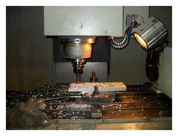
A complicated five-axis part may be easy to machine but difficult to inspect if critical features are not accessible to the measurement system.
This is why machining and inspection planning should happen together.
Depending on the part, verification may include:
- CMM measurement;
- optical measurement;
- bore gauges;
- height gauges;
- micrometers;
- surface roughness measurement;
- dedicated fixtures.
When features are controlled relative to one datum structure, the inspection method should preserve that relationship.
For complex multi-face components, CMM measurement is often useful because several surfaces and hole positions can be evaluated within one coordinate system.
When You Should Choose 3-Axis CNC Machining
3-axis machining is usually the better choice when:
- most features are accessible from one or two orientations;
- geometry is primarily prismatic;
- no continuously changing tool orientation is required;
- long tool reach is not a major problem;
- critical tolerance relationships do not span many setups;
- production economics favor simple repeatable fixtures.
Typical examples include:
- brackets;
- plates;
- standard housings;
- fixture components;
- simple mold inserts;
- covers;
- mounting blocks.
The goal should not be to use the most advanced machine available.
It should be to use the simplest process that reliably satisfies the drawing.
When You Should Choose 5-Axis CNC Machining
5-axis machining becomes more attractive when:
- the part contains features on several orientations;
- several critical features must remain related across different faces;
- geometry contains compound angles;
- deep features would otherwise require long tools;
- the cutter or holder cannot access the surface from a fixed direction;
- complex curved surfaces require changing tool orientation;
- repeated manual repositioning would create excessive setup risk.
Typical examples include:
- impellers;
- turbine blades;
- aerospace structural components;
- robotic housings;
- medical instruments;
- complex optical mounts;
- multi-face precision housings;
- complex mold components.
A Practical Selection Guide
A useful decision process is to ask the following questions in order.
1. Can every feature be reached on a 3-axis machine?
If yes, continue evaluating 3-axis machining.
If not, determine whether repositioning, 4-axis indexing, or 5-axis machining solves the access problem.
2. How many setups are required?
One or two setups normally favor 3-axis machining.
If geometry requires five or six repositioning operations, a multi-axis strategy deserves closer consideration.
3. Are critical dimensions related across those setups?
If yes, every datum transfer becomes more important.
Reducing setups may improve process reliability.
4. Will tool reach create rigidity problems?
If deep features force excessive tool overhang, 5-axis orientation may improve the process even when the geometry itself can theoretically be machined in three axes.
5. Does tool orientation need to change during cutting?
If yes, the part may genuinely require simultaneous 5-axis machining.
6. What is the production quantity?
Quantity influences whether dedicated fixtures or flexible multi-axis setups provide the better economics.
The Decision Is About Process Risk, Not Prestige
There is sometimes a tendency to treat five-axis machining as a premium version of ordinary CNC machining.
That is not a useful engineering perspective.
A five-axis machine is simply another manufacturing tool.
When geometry requires it, five-axis machining can reduce setups, improve access, shorten tools, and simplify tolerance control.
When geometry does not require it, the additional machine cost and programming effort provide little benefit.
Likewise, selecting a 3-axis process simply because it has a lower hourly rate can also be misleading if the part requires multiple complex fixtures and repeated alignment.
The best machining process minimizes the total manufacturing risk while meeting cost, quality, and lead-time requirements.
How 6CNC Selects Between 3-Axis, 4-Axis, and 5-Axis Machining
At 6CNC, machine selection begins with the component rather than with the machine.
For prototype and small-batch projects, the engineering review considers:
- part geometry;
- feature accessibility;
- datum structure;
- GD&T;
- setup count;
- tool reach;
- workholding;
- material;
- production quantity;
- inspection requirements.
A simple aluminum housing may be routed to a 3-axis machining center because that is the fastest and most economical process.
A multi-face robotic component may be better suited to indexed 5-axis machining because several critical features can remain in one setup.
An impeller or complex aerodynamic surface may require simultaneous five-axis motion because the tool orientation must change continuously.
In other cases, 4-axis machining may provide the best balance.
The objective is not to maximize axis count. It is to choose a process that produces the required geometry and tolerance reliably while keeping unnecessary machining cost out of the project.
Final Thoughts
The difference between 3-axis and 5-axis CNC machining is not simply that one machine can move in three directions and the other can move in five.
The real difference is how those additional axes change the manufacturing strategy.
3-axis machining remains highly effective for accessible, prismatic geometry and should be the default choice when the part can be produced with a small number of stable setups.
Five-axis machining becomes valuable when tool access, compound angles, deep features, complex surfaces, or multi-face tolerance relationships make conventional setups inefficient or risky.
And between the two sits 4-axis machining, which is often ideal when geometry is distributed around one controlled rotary axis.
For engineers and buyers, the best question is therefore not:
“Is 5-axis better than 3-axis?”
It is:
“Which machining strategy produces this specific part with the fewest unnecessary setups, stable tooling, reliable tolerance control, and the best total manufacturing cost?”
If you are unsure whether your component should be produced using 3-axis, 4-axis, 3+2, or simultaneous 5-axis machining, send 6CNC your CAD model and engineering drawing. Our team can review the geometry, tolerance relationships, material, quantity, and inspection requirements and recommend an appropriate manufacturing route.
Upload Your CAD Files → Request a CNC Machining Quote
Frequently Asked Questions
Is 5-axis CNC machining better than 3-axis machining?
Not for every part. Five-axis machining provides more tool orientation and can reduce setups on complex components, but 3-axis machining is often faster and more economical for accessible prismatic geometry.
Is 5-axis CNC machining more accurate?
Not automatically. Accuracy depends on machine condition, workholding, tooling, process control, temperature, and inspection. Five-axis machining can improve feature-to-feature consistency when it reduces re-clamping and datum transfers.
What is the difference between 3+2 and simultaneous 5-axis machining?
In 3+2 machining, the rotary axes position the part and remain fixed while three-axis machining occurs. In simultaneous five-axis machining, the rotary and linear axes move together continuously during cutting.
Can a 3-axis CNC machine produce complex parts?
Yes. Three-axis machines can produce complex pockets, contours, molds, and precision features. The main limitation is tool access and the number of setups required to reach different orientations.
When should I use 5-axis machining?
Use five-axis machining when the part has difficult multi-face access, compound angles, deep cavities requiring long tools, complex freeform surfaces, or critical tolerances spanning several orientations.
Is 5-axis machining more expensive?
The hourly machine rate is normally higher, but total part cost may be lower on complex parts because five-axis machining can reduce fixtures, setups, manual handling, and scrap risk.
Does five-axis machining reduce cycle time?
Sometimes. The largest savings often come from reducing setup and handling time rather than simply increasing cutting speed. Tool orientation may also allow shorter cutters and more efficient cutting parameters.
What kinds of parts are best suited to 3-axis machining?
Typical examples include mounting plates, brackets, simple housings, fixtures, covers, and prismatic components where most features are accessible from one or two orientations.
What kinds of parts are best suited to 5-axis machining?
Impellers, turbine blades, aerospace structures, complex medical components, robotic housings, optical mounts, and multi-face precision components are common examples.
When should I choose 4-axis instead of 5-axis machining?
Four-axis machining is useful when features are distributed around one primary rotary axis, such as radial holes, flats, slots, and features around shafts or cylindrical bodies. Full five-axis capability may be unnecessary if only one rotary direction is required.
Do tight tolerances always require five-axis machining?
No. A tight dimension contained entirely within one stable setup can often be produced accurately on a 3-axis machine. Five-axis machining becomes more beneficial when tight geometric relationships span multiple faces or orientations.
What files should I send to determine the correct machining process?
Send the 3D CAD model together with the controlled 2D engineering drawing. Include material, quantity, finish, tolerances, datums, GD&T, and any special inspection requirements.