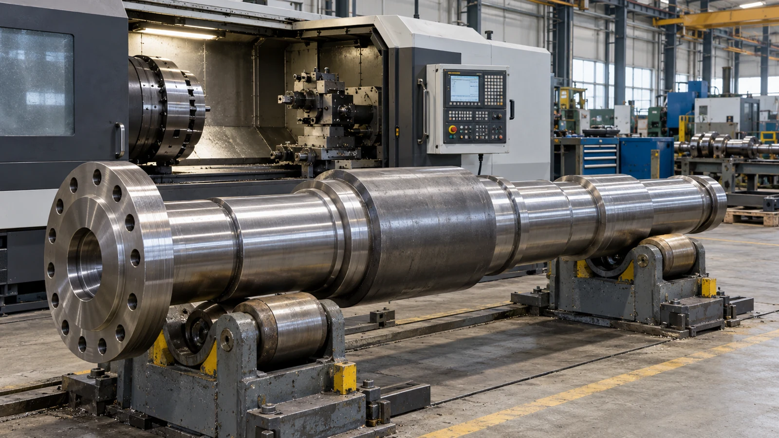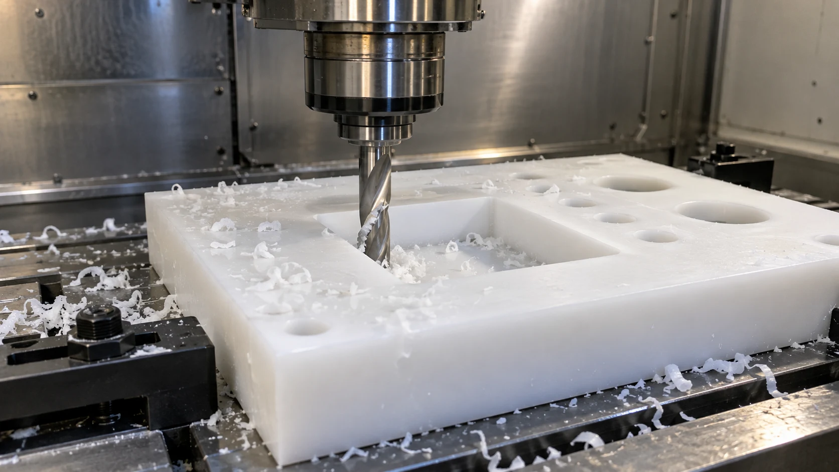
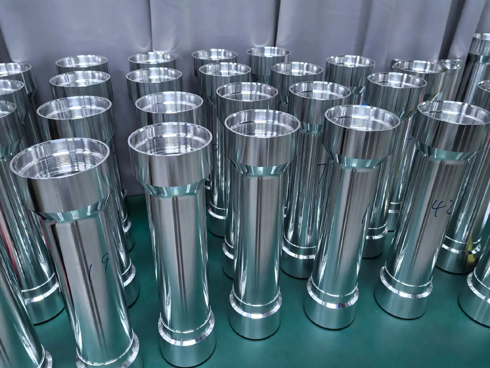
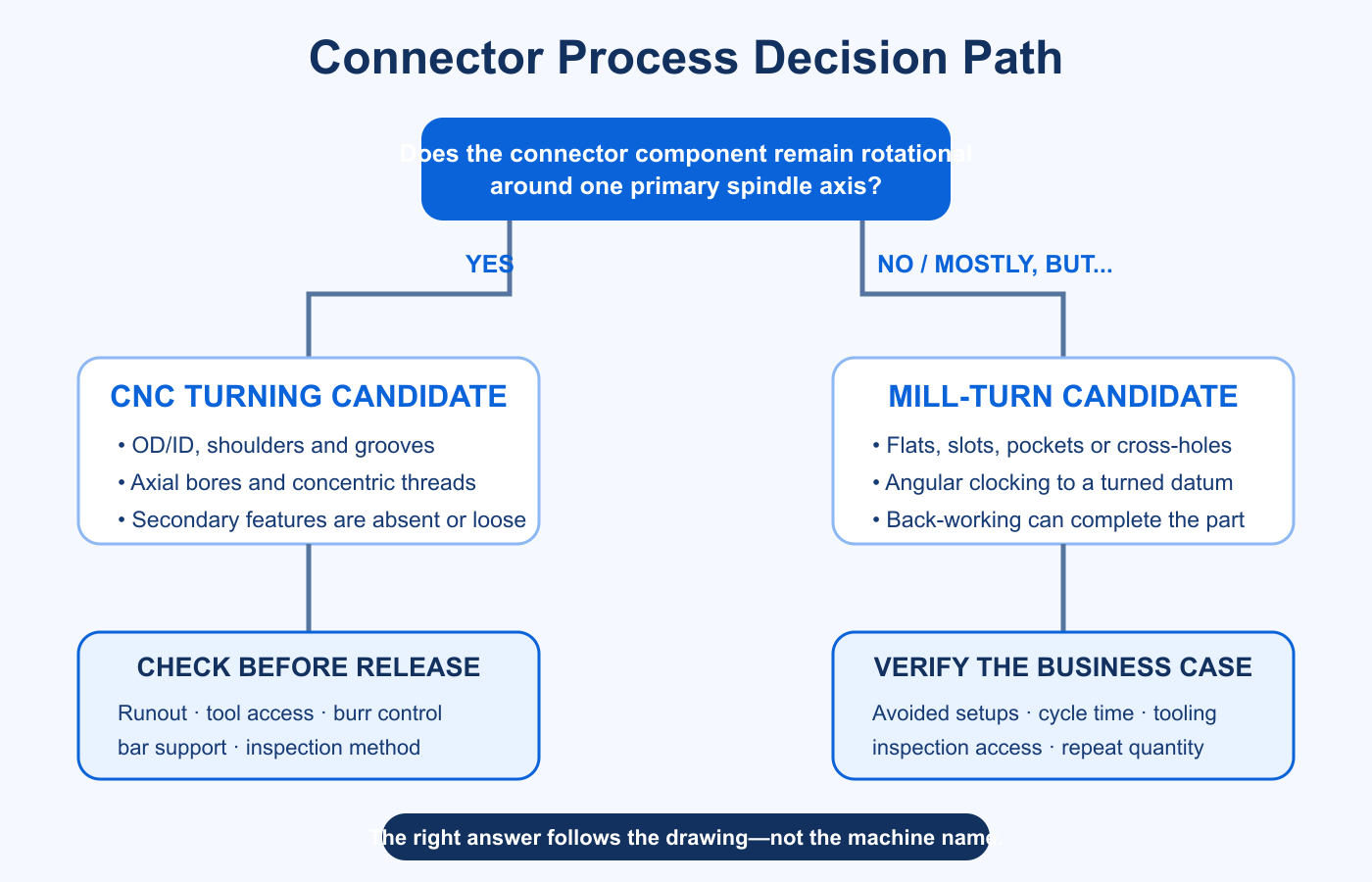
CNC turning is usually the better process for connector contacts, pins, sleeves, and bodies that remain rotational around one primary axis. Mill-turn becomes valuable when the same part also needs flats, slots, radial holes, wrench features, off-axis threads, or back-working—and when those features must remain accurately related to the turned datums.
The decision should not begin with which machine sounds more advanced. It should begin with the drawing: which surfaces establish the mating axis, which features require angular orientation, which dimensions are affected by plating, and which relationships would be exposed to error if the part moved to a second setup.
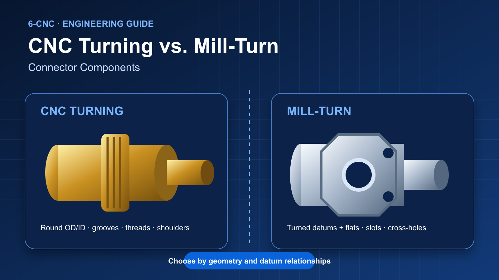
CNC Turning vs. Mill-Turn at a Glance
Conventional CNC turning and mill-turn both begin with a rotating workpiece. The difference is how much non-rotational work can be completed without transferring the component to a separate milling setup. That distinction matters for connector parts because electrical and mechanical performance often depends on relationships between the turned mating axis and secondary features.
Which Connector Components Suit CNC Turning?
CNC turning is the natural starting point when the important geometry is coaxial. The spindle axis can establish the outside diameter, bore, shoulders, grooves and threads in one coordinated sequence. This makes turning especially suitable for parts whose function depends on round mating features and controlled diameter relationships.
- Machined contacts and pins: stepped diameters, contact bands, crimp or solder features, retention grooves and axial bores.
- Sockets and sleeves: controlled ID/OD relationships, thin walls, entry chamfers and internal contact features.
- Ferrules and spacers: simple rotational components with length, diameter and surface-finish requirements.
- Threaded connector bodies: cylindrical bodies whose wrenching or mounting features are absent or can tolerate a separate operation.
A separate secondary operation is not automatically a problem. If the milled feature has a generous positional tolerance, can be located from a reliable turned datum, and does not affect electrical or sealing performance, conventional turning plus a simple milling fixture may remain the lower-risk and lower-cost route.
When Mill-Turn Becomes the Better Choice
Mill-turn is most useful when the part is fundamentally rotational but cannot be completed as a reliable connector component through turning alone. Live tooling and controlled spindle positioning can add flats, radial holes, slots and off-axis features while the primary turned datums remain established.
- A wrench flat or key must be clocked to a thread start, slot or internal feature.
- Radial holes or slots require position control relative to the mating bore or OD.
- Back-working can finish the cutoff end and reduce an additional chucking operation.
- Re-gripping a thin-walled brass, copper or aluminum body could distort the part.
- A separate fixture would be difficult to locate, validate or maintain across repeat batches.
The Real Issue Is Datum Transfer
A process transfer introduces another location system. The second machine or fixture must find the part from surfaces produced earlier, and any clearance, contamination, burr, jaw pressure or locating error can affect the new features. That does not make secondary setups unacceptable; it means their error contribution must fit inside the functional tolerance budget.
For connector bodies, the critical question is often not whether a flat is within its own size tolerance. It is whether that flat, radial hole or mounting feature is correctly related to the mating bore, sealing diameter, thread or contact axis. If the relationship is tight, producing both feature groups without releasing the primary datum can simplify control.
Cost: Fewer Setups Do Not Automatically Mean a Lower Price
Mill-turn can remove handling, fixtures, work-in-process queues and datum-transfer risk. But it can also require more capable equipment, more programming, additional driven tools and a longer cycle. A sound comparison considers total process cost rather than counting operations.
- Turning-only route: machine time, cutoff or back-work, any secondary fixture, transfer labor and inspection between operations.
- Mill-turn route: programming, live-tool cycle time, tool stations, machine rate, bar-feed strategy, sub-spindle work and final inspection.
- Risk cost: expected scrap, rework, fixture maintenance, mixed revisions and measurement effort.
For a simple pin, mill-turn is usually unnecessary. For a connector body with several tightly related radial and axial features, avoiding two custom fixtures and repeated handling may outweigh the higher machine rate. Quantity also matters: a complex one-off prototype may favor flexible completion, while a stable repeat part may justify optimized dedicated tooling.
Material, Burr and Plating Considerations
Connector components are commonly machined from brass, copper alloys, aluminum and stainless steel. The selected material affects chip control, tool wear, wall stability, burr formation and the surface condition delivered to plating.
Cross-holes and slots can create internal burrs at intersections. Completing these features on a mill-turn machine may improve positional control, but it does not eliminate the need for a defined deburring method and inspection. The drawing should identify contact surfaces, sealing edges, thread starts and other zones where edge damage or residual burrs are unacceptable.
Plated connector parts also need clear pre-plate and post-plate dimensions. A better machine cannot resolve an ambiguous drawing. For material and coating guidance, see our connector contact machining guide.
Inspection Must Match the Process Decision
Reducing setups can improve process consistency, but it does not prove that the part meets the drawing. The inspection plan should verify the feature relationships that justified the process choice.
Common Mistake: Specifying Mill-Turn Without a Functional Reason
Example: A buyer specifies mill-turn for a brass connector sleeve because the part includes two wrench flats. The flats have a broad tolerance and no controlled angular relationship to the bore or thread.
Why this can be wasteful: conventional turning plus a simple secondary fixture may meet every functional requirement at lower programming and machine cost. The correct request is to control the functional relationships on the drawing and let the manufacturing review compare routes.
Process Review Checklist
Decision Matrix
- Choose CNC turning when the important geometry remains rotational and any secondary features are absent, loose or economically fixtureable.
- Choose mill-turn when flats, slots, cross-holes or back features must remain closely related to the turned axis, or when transfer creates unacceptable handling or distortion risk.
- Compare both routes when setup reduction is attractive but the added live-tool cycle, programming or machine cost may outweigh the benefit.
Frequently Asked Questions
Is mill-turn always more accurate than CNC turning? No. Turning is highly effective for coaxial features. Mill-turn is advantageous when non-rotational features need controlled relationships to the turned datums. Accuracy still depends on tooling, workholding, material, thermal control and inspection.
Can a conventional lathe make connector bodies with flats? The turned geometry can be made on the lathe and the flats added in a secondary milling operation. Whether that is the best route depends on their tolerance, angular relationship, quantity and fixture requirements.
Does one-setup machining eliminate inspection? No. It can reduce transfer variation, but the resulting feature relationships still require verification against the drawing datums.
What files are needed for a process comparison? Send a solid 3D model, controlled 2D drawing, material and condition, plating or finish specification, quantities, critical-feature notes and required inspection records.
Review a Connector Component
6CNC provides connector machining services for contacts, pins, sockets, threaded bodies, housings and related interface parts. Send the CAD model and drawing for a practical comparison of turning, mill-turn, tolerance, plating allowance, burr control and inspection requirements.
The practical choice is simple: use the least complex process that can reliably hold the functional relationships on the drawing. For many contacts and sleeves, that is CNC turning. For connector bodies that combine turned datums with tightly controlled off-axis features, mill-turn may provide the better total process.