Executive Summary: The 30-Second Engineering Check
- CNC Milling: Optimized for prismatic, non-axisymmetric geometries. Material remains stationary while rotating cutters remove stock across discrete coordinate axes.
- CNC Turning: Optimized for rotational symmetry around a central datum axis. Workpiece rotates against stationary inserts. Holds tighter coaxial runout tolerances at lower cost per piece in volume.
- The Single-Setup Principle: Design components to maximize feature generation within one operational clamping cycle. Eliminating part re-fixturing prevents compounding datum stack-up errors.
- Mill-Turn Selection: High efficiency for hybrid designs, but carries increased hourly machine rates and programming overhead. Limit to high-complexity or medium-to-high volume scenarios.
1. Kinematic Foundations: How Material is Sheared
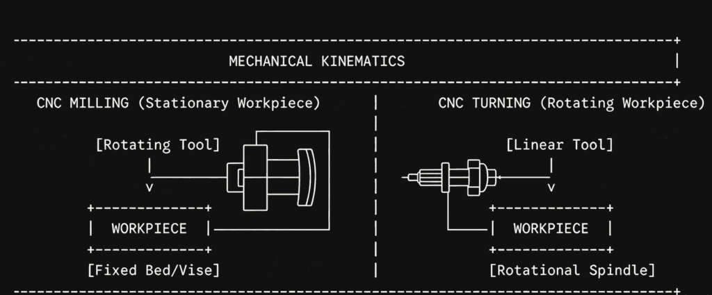
To understand which process suits a given design, one must first isolate the relative motion between the cutting tool and the workpiece. The mechanical efficiency, tool wear patterns, and achievable surface topology of each method stem directly from these kinematics, defined by industrial standards like ASM International’s metal cutting specifications.
CNC Milling Mechanics
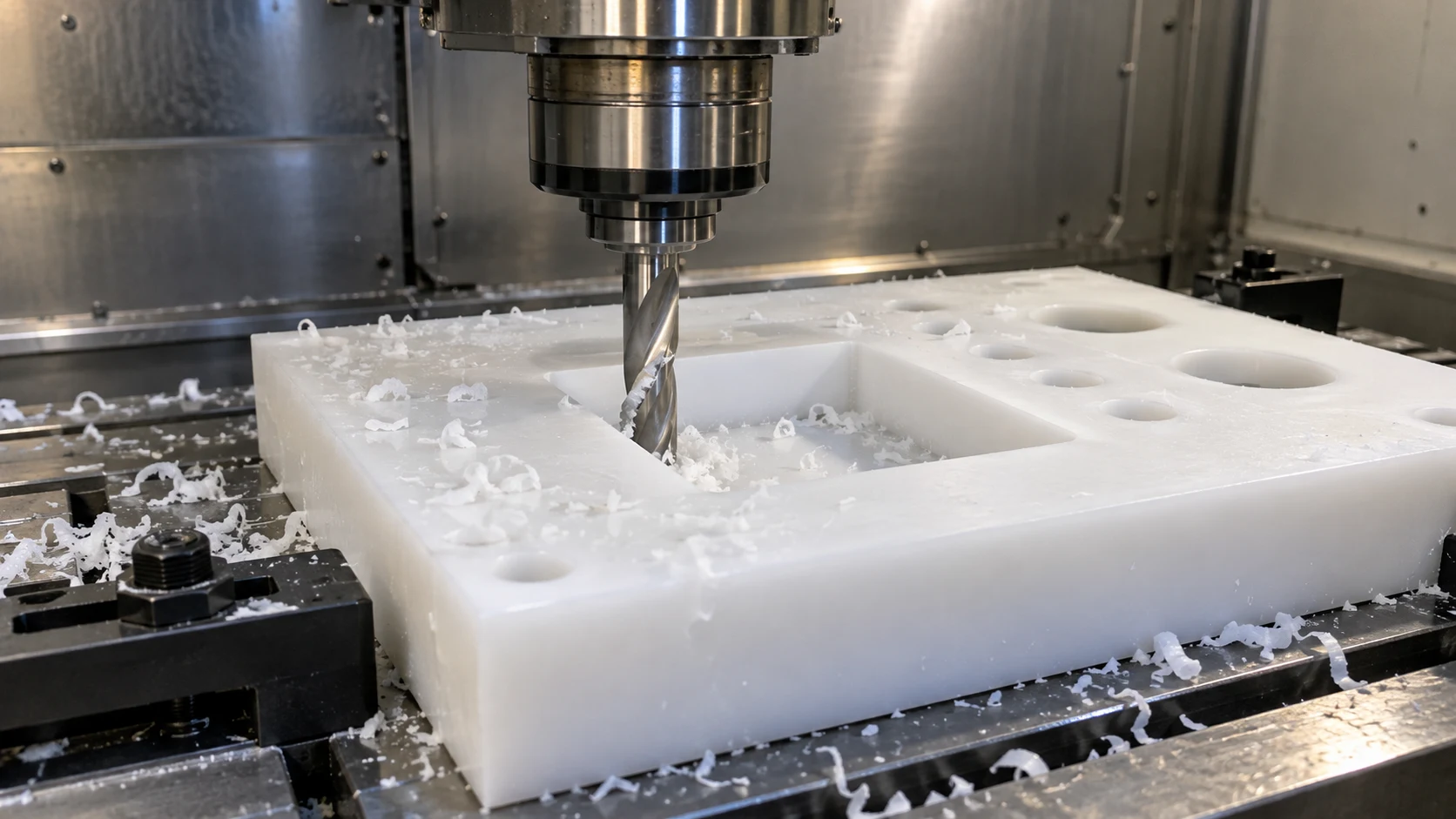
In a standard CNC milling configuration ($3\text{-axis}$ to simultaneous $5\text{-axis}$), the raw material is secured to the machine bed using a vise, custom fixtures, or a vacuum chuck. The material remains mechanically stationary relative to its localized coordinate system.
Material removal is executed by a cutting tool (e.g., end mills, face mills, or drills) rotating at high angular velocities ($RPM$). The machine’s axes move the rotating spindle along linear paths ($X$, $Y$, and $Z$) and, in multi-axis setups, rotate the workpiece or spindle housing to present the cutting tool to multiple faces of the part. The cutting action in milling is inherently intermittent, causing cyclical thermal and mechanical loading on the cutter.
CNC Turning Mechanics
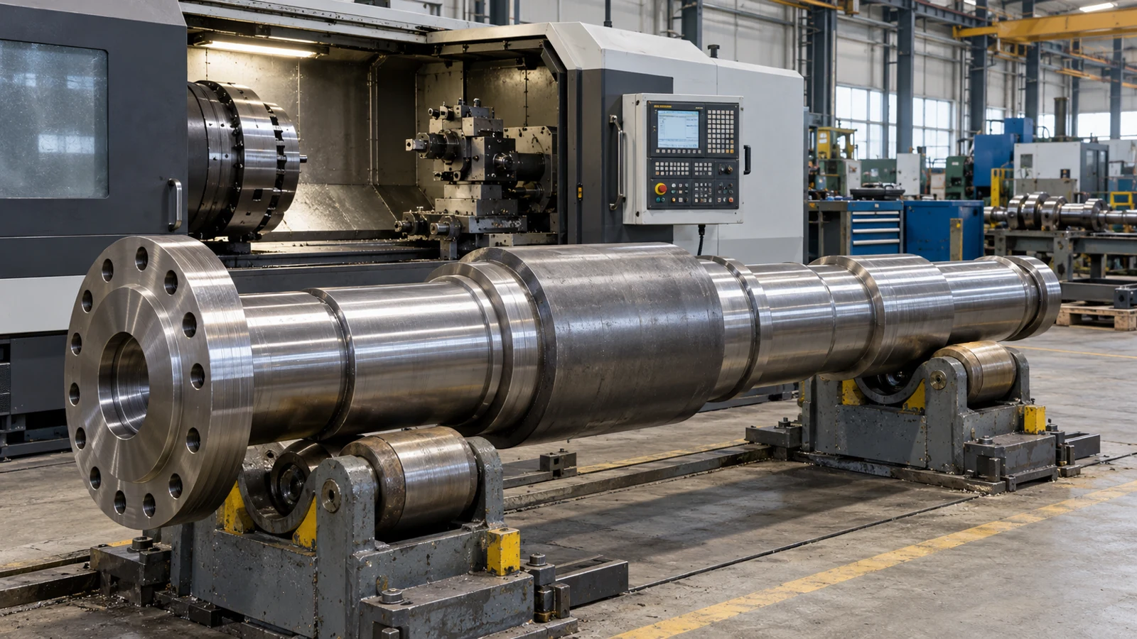
Conversely, CNC turning operates on a rotational paradigm. The raw stock—typically cylindrical bar stock fed through a collet or clamped in a 3-jaw chuck—is rotated at high speeds by the machine’s main spindle.
The cutting tool itself remains rotationally stationary. It is mounted in a rigid tool turret and moves linearly along the workpiece’s axis of rotation ($Z\text{-axis}$) and perpendicular to it ($X\text{-axis}$). Because the tool remains in continuous contact with the rotating workpiece during a cut, turning features continuous cutting action. This results in uniform chip formation and distinct continuous-spiral surface finishes ($Ra$) regulated by the ISO 21920 surface texture standards.
2. The Geometric and Volume Decision Tree
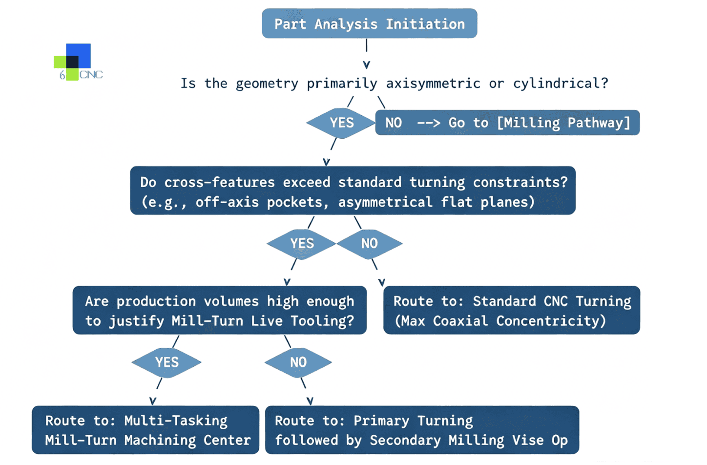
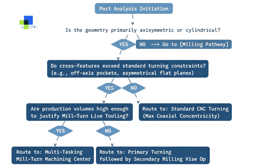
When evaluating a new technical drawing or STEP file for production routing, engineers must deploy a systematic logic framework that factors in both part quantity and geometry.
Analytical Logic Gates
Logic Gate 1: Production Volume Filter
- Low-Volume Prototype ($<10$ pieces): Lean toward precision CNC milling unless the part is purely axisymmetric. Setting up a CNC mill with standard soft jaws is often faster and more cost-effective than configuring custom turned-part turn-downs and specialized lathe tooling for small runs.
- Production-Volume ($>100$ pieces): If the part has any significant axial symmetry, route to turning. Material utilization from continuous bar feeders and fast cycle times yield lower piece costs.
Logic Gate 2: Axial Symmetry & The Envelope Matrix
If the production volume justifies the routing, analyze the bounding box. If a part can be generated by revolving a 2D profile around a central datum line, it is inherently a turning candidate. If the part is box-like, features vast planar surfaces, or exhibits asymmetric 3D topography, it must be routed to a milling center.
Logic Gate 3: Cross-Feature Evaluation
Many cylindrical parts feature non-cylindrical elements—such as bolt circle holes, wrench flats, keyways, or off-axis slots. If these features are minor, they can be processed on a CNC lathe with live tooling. If the cross-features require extensive pocketing or three-dimensional profiling, the part must either be transferred to a mill as a secondary operation or run completely on a 5-axis machining center.
Logic Gate 4: Geometric Tolerances ($GD\&T$)
If the engineering drawing dictates ultra-tight concentricity, runout, or cylindricity between multiple coaxial diameters, turning is required. Machining all diameters in a single chucking operation minimizes setup error and ensures coaxial alignment based on ISO 2768 general tolerances.
3. High-Intent Technical Comparisons
The table below contrasts the operational and capability deviations between industrial-grade CNC milling and turning centers.
| Operational Metric | CNC Milling Centers | CNC Turning Centers (Lathes) |
| Primary Bounding Geometry | Prismatic, Block-like, Cuboidal, Organic 3D | Cylindrical, Conical, Axisymmetric, Tubular |
| Material Form Factor | Rectangular Billet, Castings, Plate Stock | Round Bar Stock, Hex Bar, Tube Stock |
| Axis Configurations | $3\text{-Axis}$, $4\text{-Axis}$, 5-Axis Simultaneous Milling | $2\text{-Axis}$, $3\text{-Axis}$ ($X, Z +$ Live Tooling), Multi-Turret |
| Typical Volumetric Accuracy | $\pm 0.005\text{ mm}$ to $\pm 0.012\text{ mm}$ | $\pm 0.002\text{ mm}$ to $\pm 0.008\text{ mm}$ |
| Achievable Surface Finish ($Ra$) | $0.8\ \mu\text{m} – 3.2\ \mu\text{m}$ | $0.4\ \mu\text{m} – 1.6\ \mu\text{m}$ |
| Primary Clamping Setup | Vise, step-clamps, modular fixture plates | 3-jaw chuck, emergency collets, step chucks |
4. Engineering Case Studies: Real-World Part Routing
Case Study A: The Aerospace Avionics Enclosure (CNC Milling Optimized)
- Component Architecture: A thin-walled, rectangular heat-sink housing designed to protect flight instrumentation.
- Material Specifications: Aluminum 6061-T6 block stock.
- Geometric Features: Deep internal pocketing to remove $85\%$ of the raw material mass, integrated exterior cooling fins ($1.5\text{ mm}$ thickness), and 24 perimeter-tapped holes ($\text{M}3 \times 0.5$) spread across four distinct planes.
- Process Analysis: This component is completely devoid of axial symmetry. The part is routed to a high-speed 5-Axis CNC Milling Center.
- Execution Strategy: Simultaneous 5-axis capabilities allow the cutting tool to articulate perpendicular to the side walls, machining the deep pockets and thin cooling fins. This maintains parallelism tolerances between the internal mounting brackets and external datum faces within $\pm 0.01\text{ mm}$.
Case Study B: The High-Pressure Fluid-Handling Valve Stem (CNC Turning Optimized)
- Component Architecture: A variable-diameter control shaft utilized in subsea oil and gas metering systems.
- Material Specifications: Nitronic 50 Stainless Steel (High-strength, corrosion-resistant austenitic stainless steel).
- Geometric Features: A $250\text{ mm}$ stepped shaft featuring four distinct outer diameters ($OD$), a highly precise taper ($8^\circ \pm 0.05^\circ$), a continuous sealing surface requiring a $Ra\ 0.4\ \mu\text{m}$ finish, and a pair of dual wrench flats on the non-sealing end.
- Process Analysis: The component is overwhelmingly axisymmetric. The tight concentricity requirement between the sealing diameters ($\pm 0.003\text{ mm}$) dictates that the part must spin on a single, continuous spindle axis to eliminate structural runout.
- Execution Strategy: The part is routed to an advanced CNC Turning Center with Live Tooling. The main turning profiles, tapers, and precision sealing surfaces are machined continuously. To execute the wrench flats, the spindle locks into a specific angular index ($C\text{-axis}$ configuration), and a rotating end mill mounted in the live-tool turret advances to face off the flats.
5. Critical Design for Manufacturing (DFM) Guidelines
The Fundamental Rule: The Single-Setup Principle
Every additional part rotation, jaw change, or physical machine transfer introduces positioning variability. Always design parts so that the majority of critical, inter-dependent tolerances can be machined in one single setup. Minimizing back-side indexing or multi-angle secondary steps prevents compounding datum stack-up errors—a foundational principle emphasized in our comprehensive DFM review process.
CNC Milling DFM Controls
1. Internal Vertical Corner Radii
Because milling cutters are round, they inherently leave a radius equal to the radius of the tool. Sharp $90^\circ$ internal vertical corners require expensive secondary processes like Electrical Discharge Machining (EDM).
- DFM Parameter: Specify an internal radius that is at least $10\%\text{ to }15\%$ larger than the radius of the standard milling cutter intended for the feature. If a pocket is $20\text{ mm}$ deep, a robust $10\text{ mm}$ diameter tool should be used to prevent deflection. Design the corner radius to be $\ge 5.5\text{ mm}$ instead of exactly $5\text{ mm}$. This allows the tool to navigate the corner dynamically rather than coming to an abrupt directional stop, which induces tool chatter and mars the surface finish.
2. Pocket Depth-to-Width Ratios
Deep, narrow pockets require long, slender end mills. As an end mill’s reach increases, its structural deflection increases exponentially as a cubic function of its length ($L^3$).
- DFM Parameter: Limit internal cavity depths to 4x the cutter diameter. Cavities exceeding a 4:1 aspect ratio force aggressive reductions in feed rates and require specialized anti-vibration carbide tooling, elevating machine cycle times.
CNC Turning DFM Controls
1. Aspect Ratios and Part Deflection ($L/D$)
When a long, slender cylindrical part is spun at high speeds in a lathe, the lateral pressure exerted by the cutting tool causes the material to flex away from the cutting edge. This deflection results in structural taper errors where the center of the shaft is thicker than the ends.
- DFM Parameter: For unsupported turned parts, maintain a length-to-diameter ($L/D$) ratio of $\le 4:1$. If your design dictates an $L/D$ ratio greater than 4:1, production requires a tailstock or steady rest to stabilize the part. Ensure your part design accommodates a center-drill hole on the face if a tailstock support is required.
2. Thread Relief Insets
When turning an external thread up to a shoulder or a stepped face on a lathe, the single-point threading tool cannot cut perfect threads directly flush against the blocking wall. The tool requires a physical exit zone to decelerate and pull out of the cut.
- DFM Parameter: Incorporate a thread relief groove between the threaded section and the shoulder. This groove should have a diameter slightly smaller than the minor diameter of the thread and a width equivalent to at least $1.5\text{ to }2$ thread pitches.
6. Hybrid Solutions: The Mill-Turn Flow and Constraints
Modern manufacturing often blurs these lines through multi-tasking technology. These advanced machines feature standard lathe spindles to rotate the part, alongside fully articulate milling heads ($B\text{-axis}$ and live tooling) and sub-spindles to complete the entire component in a single setup.
Cost and Complexity Constraints
While Mill-Turn machining reduces physical handling and eliminates tooling fixtures, it carries specific operational thresholds:
- Higher Machine Rates: Mill-Turn equipment carries a substantially higher capital cost than standard vertical machining centers or basic lathes. This increases the hourly machine rate, making simple parts inefficient for this routing.
- Programming Overhead: Multi-turret, multi-spindle programming requires intensive CAM synchronization and collision simulation. Setup and programming costs are high.
- Optimal Selection Criterion: Reserve Mill-Turn routing exclusively for parts with medium-to-high geometric complexity combined with medium-to-high production volumes ($>50\text{ pieces}$ per run), where the labor savings from eliminating secondary setups outweigh the premium machine rates. Low-volume, simple parts should be routed to separate machines.
7. Operational Alignment with the 6CNC Capability Matrix
The production ecosystem at 6CNC is engineered around precise mechanical validation:
- Precision CNC Milling Services: Equipped with high-speed 3, 4, and 5-axis vertical and horizontal machining centers. We hold linear tolerances down to $\pm 0.005\text{ mm}$ across complex prismatic enclosures and organic profiles, maintaining native surface finishes down to $Ra\ 0.8\ \mu\text{m}$.
- Advanced CNC Turning Services: High-precision lathes paired with sub-spindles and multi-axis live tooling allow us to process complex turned parts with secondary cross-drilling and flat milling in a single handling, maintaining concentricity requirements down to $\pm 0.002\text{ mm}$ on critical bearing profiles.
- Material Breadth: Fully equipped to process challenging industrial materials ranging from standard Aircraft Aluminum (7075-T6) and Stainless Steels (316L, 17-4 PH) to exotic Superalloys (Inconel 718, Titanium Grade 5, and Nitronic formulations).
By integrating DFM parameters into your initial engineering design phases, you eliminate manufacturing steps and optimize cycle times. Upload your technical drawings and STEP models directly to the secure portal at 6-cnc.com for an automated DFM review and a production-grade quote.