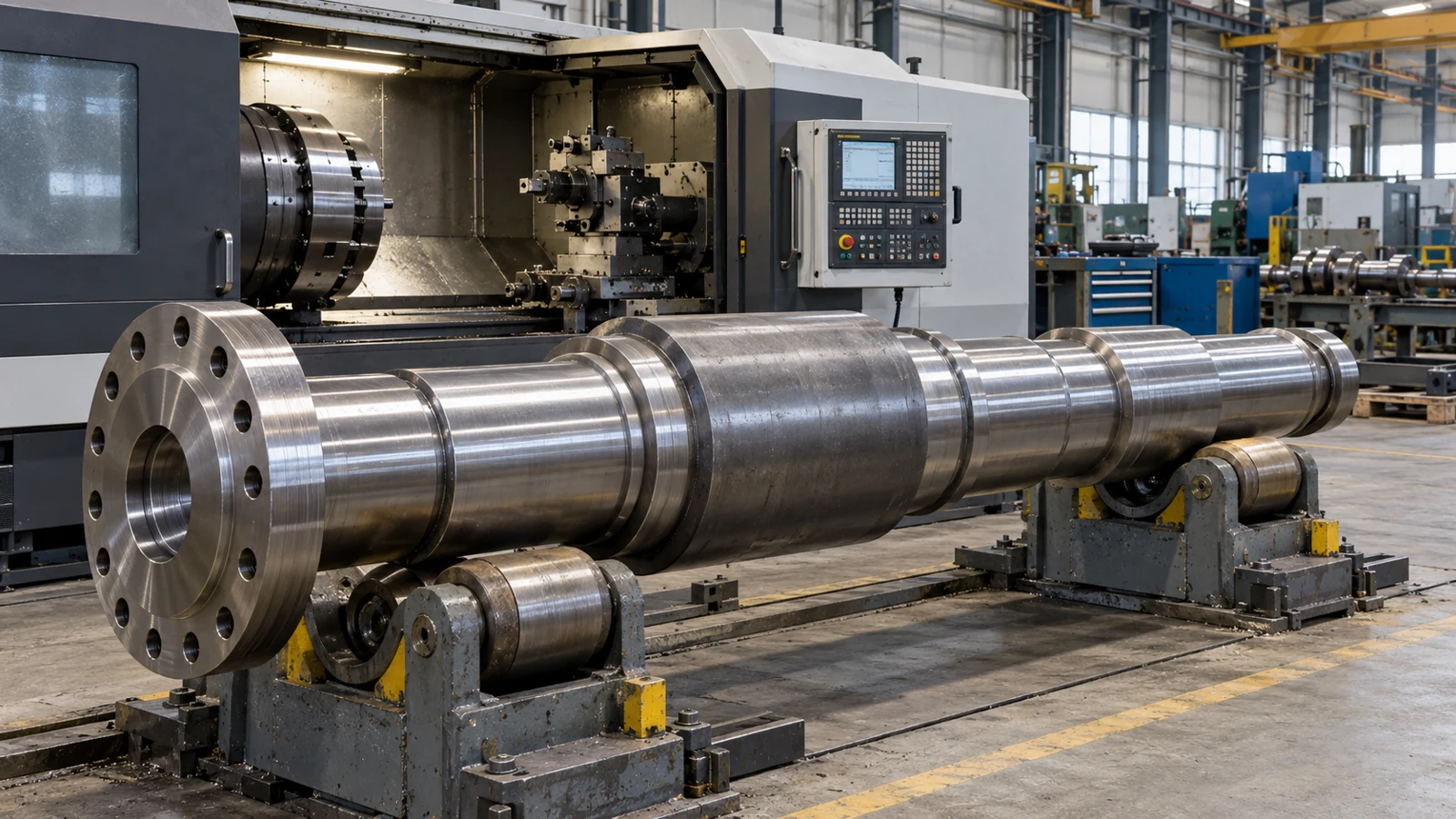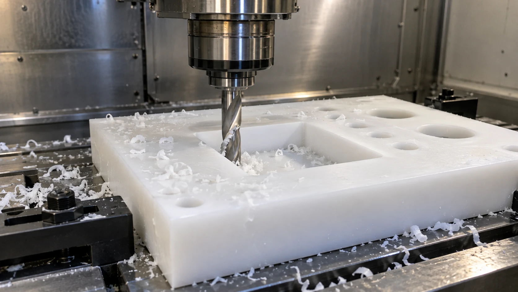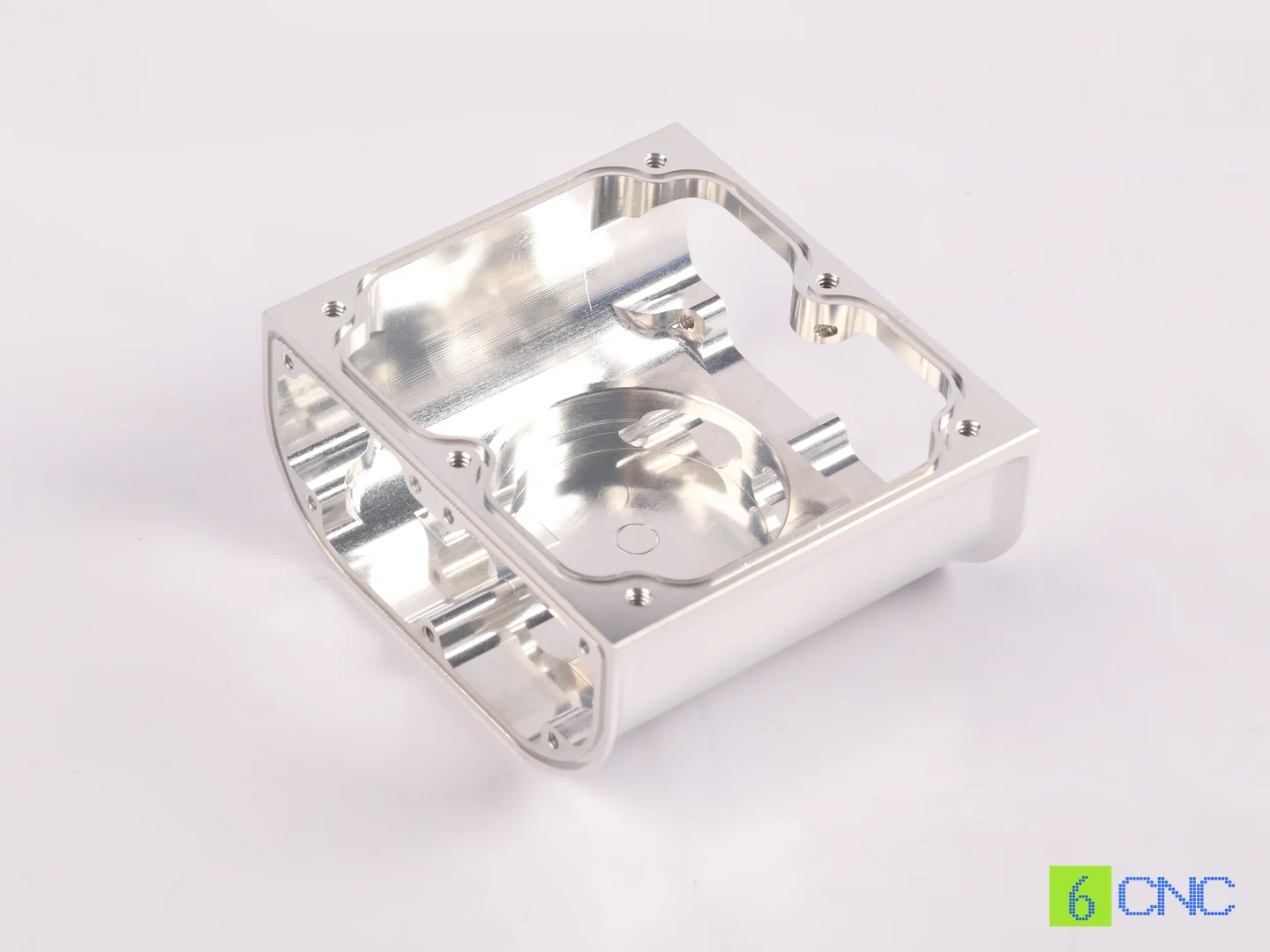
Flat faces, drilled holes, and straight pockets are relatively straightforward CNC milling features. Curved surfaces are different. As soon as a part contains continuously changing slopes, concave or convex geometry, blended radii, freeform contours, or sculpted surfaces, the relationship between the cutting tool and the workpiece changes continuously throughout the toolpath.
That makes curved-surface machining much more sensitive to cutter geometry, tool orientation, stepover, toolpath direction, machine motion, workholding, and finishing strategy. A toolpath that produces an excellent finish on a shallow region may leave visible scallops or step marks as the surface becomes steeper. A ball nose cutter that works well on one contour may cut inefficiently near its center on another.
These challenges appear in many precision components. Aerospace brackets contain blended transitions and lightweight curved walls. Medical instruments may use ergonomic freeform handles. Optical equipment requires curved mounts and housings. Robotics components frequently combine contoured external geometry with precision mounting interfaces. Mold and die components can contain even more demanding three-dimensional surfaces.
Machining these parts successfully therefore requires more than simply loading a ball nose end mill and selecting a 3D contour cycle. The complete process—from roughing through final inspection—has to be planned around the geometry of the surface.
This guide explains how CNC milling curved surfaces works, which cutting tools and toolpaths are commonly used, how 3-axis and 5-axis machining differ, what causes visible surface defects, and how to improve accuracy and finish on complex contoured parts.
What Is Curved Surface CNC Milling?
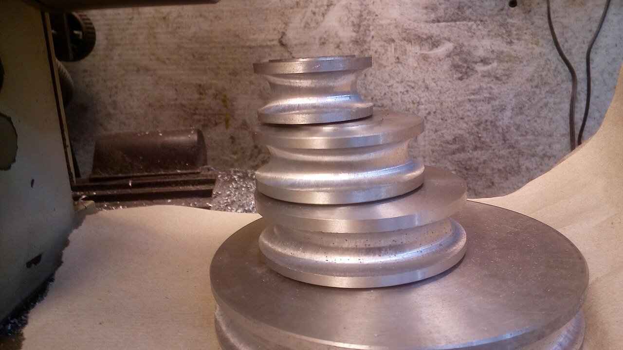
Curved surface milling is a form of 3D contour machining in which a rotating cutting tool follows a continuously changing surface rather than producing only straight walls or flat planes. The geometry may be convex, concave, cylindrical, spherical, blended, sculpted, or completely freeform.
Unlike a simple 2D pocket, the Z position of the cutting tool usually changes continuously as the cutter moves across the surface. On more complex parts, the tool orientation may also change, particularly when 5-axis machining is used.
Typical curved features include:
- aerodynamic surfaces;
- mold cavities;
- impeller blades;
- turbine-related components;
- ergonomic handles;
- orthopedic instrument geometry;
- optical housings;
- robotic arm components;
- sculpted product housings;
- blended transitions between machined features.
The challenge is that a curved surface is rarely machined in one pass. The CNC machine approximates the designed surface using thousands of closely spaced cutter movements. The spacing, orientation, and accuracy of those movements determine how closely the physical surface matches the CAD model.
If the passes are too far apart, scallops remain between them. If the tool orientation changes abruptly, visible marks can appear. If the cutter deflects, the finished contour can deviate from the nominal CAD surface even when the programmed coordinates are correct.
Why Curved Surfaces Are More Difficult to Mill
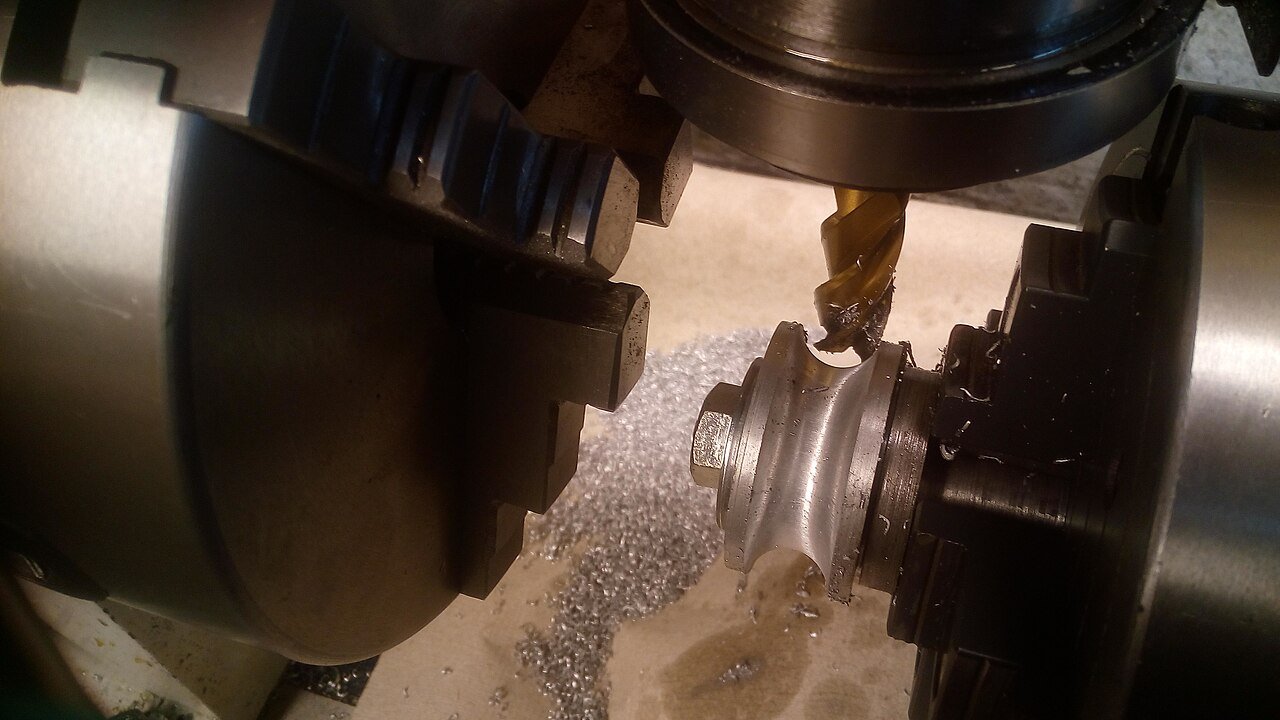
The difficulty comes from continuously changing cutting conditions.
Consider a ball nose end mill moving across a simple convex surface. At one point, the cutter may contact the workpiece near its outer diameter, where cutting speed is relatively high. A few millimeters later, the geometry may force the contact point closer to the center of the tool, where effective cutting speed decreases dramatically.
At the same time, engagement angle, tool load, chip formation, and surface direction are changing.
On a freeform component, this can happen continuously throughout the machining cycle.
Tool engagement is constantly changing
When milling a flat wall, the relationship between the cutter and surface is relatively predictable. On a curved surface, the cutter may move from shallow engagement into steeper geometry and then into a concave transition.
Cutting force changes with it.
The cutter does not contact every slope in the same way
Ball nose tools are particularly sensitive to contact position. The center of a ball nose has nearly zero surface speed at the exact tip. If the machining strategy relies heavily on that region, cutting can become more like rubbing than clean shearing.
Small toolpath errors become visible
Curved cosmetic surfaces reflect light very differently from flat surfaces. Small changes in cutter engagement, toolpath direction, tool height, or machine motion may create visible bands even when dimensional inspection shows the part is technically within tolerance.
Inspection is more difficult
A flat surface can be checked relatively easily using conventional dimensional methods. A freeform surface may require CMM scanning, comparison against CAD geometry, profile measurement, or optical inspection.
For this reason, curved-surface machining should be treated as a complete process rather than simply another CAM operation.
Roughing, Semi-Finishing, and Finishing Curved Surfaces
Trying to machine a complex surface directly from raw stock using a finishing toolpath is rarely practical. Most curved components are divided into several stages so that each machining operation performs a specific job.
Roughing
Roughing removes the majority of material and establishes the general shape of the component. At this stage, productivity and process stability are normally more important than final surface appearance.
Large-diameter end mills, indexable cutters, or high-efficiency roughing strategies may be used depending on the material and geometry. The roughing process normally leaves consistent stock around the final curved surface rather than attempting to reach the finished contour immediately.
For example, an aluminum mold cavity may be rough machined while leaving 0.5–1.0 mm of material around the final surface. The exact allowance depends on part size, material, rigidity, tolerance, and tooling.
Semi-finishing
Semi-finishing removes the uneven material left after roughing and creates a more consistent allowance before the final operation.
This stage is particularly important on complex curved parts.
If one region contains 0.1 mm of finishing stock while another contains 1 mm, the finishing cutter experiences very different loads as it moves across the part. That variation can affect deflection, surface quality, and dimensional accuracy.
Semi-finishing creates a more predictable condition for the final pass.
Finishing
Finishing creates the final surface geometry and has the greatest influence on visible tool marks and surface roughness.
The cutting tool normally removes a relatively small amount of material while following closely spaced toolpaths. At this point, cutter runout, spindle condition, stepover, tool orientation, feed stability, and workpiece rigidity become increasingly important.
Super-finishing or secondary finishing
Some molds, optical tooling, medical components, and appearance parts require a surface beyond what normal CNC finishing can economically produce.
Depending on the requirement, machining may be followed by:
- precision grinding;
- polishing;
- lapping;
- abrasive finishing;
- hand polishing;
- other specialized finishing processes.
The important point is that CNC machining does not always need to produce the entire final surface condition by itself. The machining strategy should reflect what subsequent finishing operations will accomplish.
Choosing the Right Cutting Tool for Curved Surface Milling
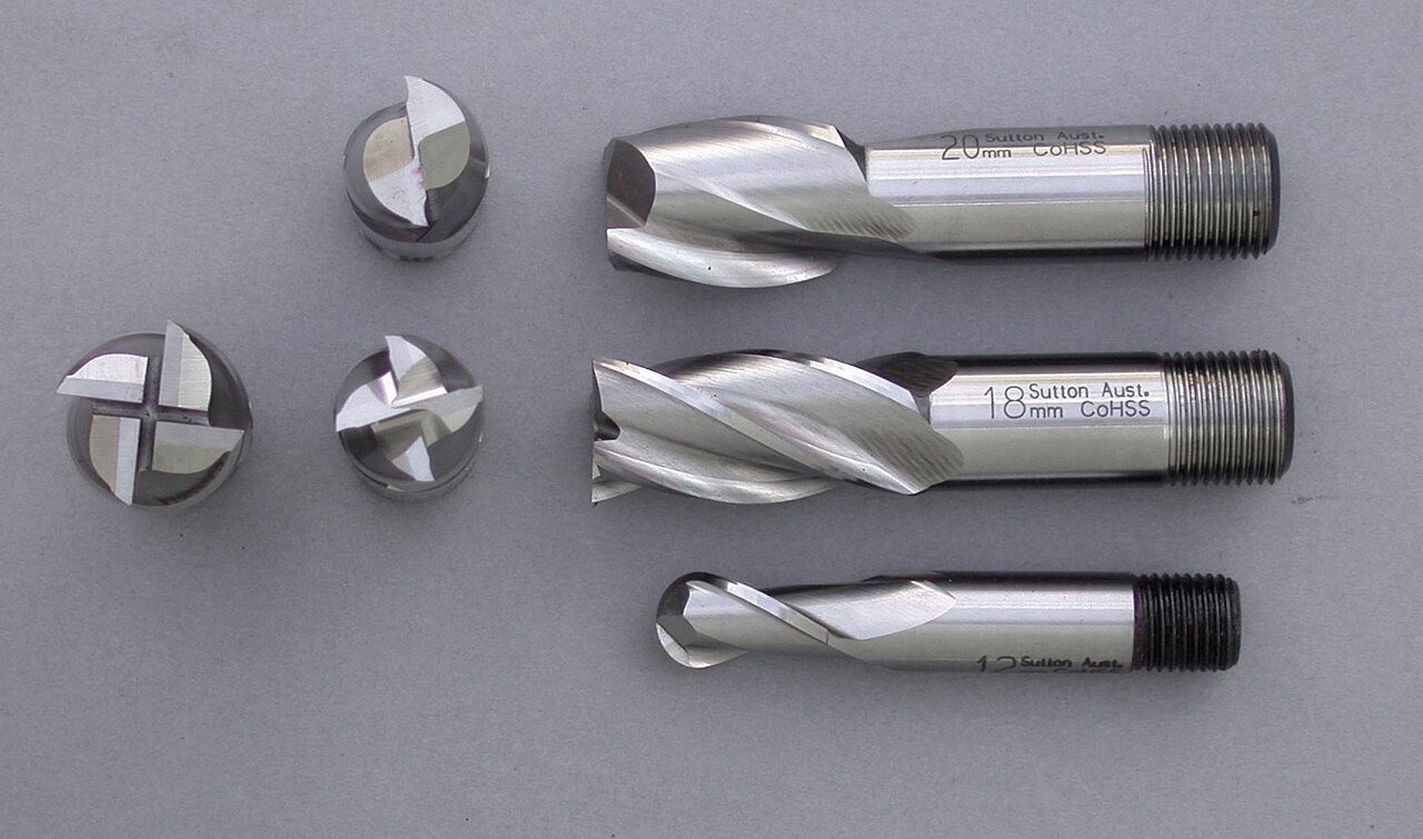
Cutting-tool geometry has a major influence on curved surface quality. Ball nose end mills are widely associated with 3D contour machining, but they are not automatically the best choice for every part.
Ball Nose End Mills
Ball nose end mills have a hemispherical cutting end and are one of the most common tools for machining curved surfaces.
Their shape allows the cutter to follow slopes and contours without leaving the sharp corner that a square end mill would create. They work particularly well for:
- mold cavities;
- convex surfaces;
- concave surfaces;
- sculpted housings;
- 3D contours;
- freeform finishing.
The main limitation comes from the center of the ball. Effective cutting speed decreases as the contact point approaches the cutter axis.
This matters especially when the tool is vertical and machining a shallow or nearly horizontal region. The center of the ball may rub against the surface rather than cut efficiently.
For this reason, the same ball nose tool may perform very well on a steep wall but poorly on the floor of a shallow curved cavity.
Bull Nose or Corner-Radius End Mills
A bull nose end mill has a flat section at the bottom combined with a corner radius.
For shallow surfaces, large open contours, and certain semi-finishing operations, it can be more productive than a full ball nose cutter because more of the effective cutting diameter remains engaged.
Bull nose tools can also offer greater rigidity.
However, they cannot follow all concave geometries because the cutter geometry must physically fit inside the surface curvature.
Round-Insert Cutters
Larger indexable cutters using round inserts are useful during roughing and semi-finishing of large curved components.
The inserts provide strong cutting edges and can remove material much faster than a small solid-carbide finishing tool.
Typical applications include large molds, dies, structural components, and other parts where a significant amount of material must be removed before final finishing.
Barrel and Lens-Shaped Cutters
Modern 5-axis machining has expanded the use of barrel, oval, lens, and other circle-segment cutters.
Instead of using a small-radius ball nose, these cutters provide a much larger effective cutting radius along part of their profile. This allows larger stepover distances while maintaining relatively small scallop heights.
On suitable steep or gently curved surfaces, a barrel cutter can reduce the number of finishing passes dramatically.
They do require more sophisticated CAM programming and machine motion, and the tool orientation must remain carefully controlled. For complex five-axis finishing, however, circle-segment tools can provide significant productivity improvements.
Ball Nose vs Bull Nose: Which Is Better?
Neither cutter is universally better.
| Requirement | Ball nose | Bull nose / corner-radius |
|---|---|---|
| Complex freeform geometry | Excellent | Good where geometry permits |
| Concave surfaces | Excellent | Limited by corner geometry |
| Shallow open surfaces | Can be inefficient near center | Often more efficient |
| Deep sculpted cavities | Very useful | Geometry-dependent |
| Surface finishing | Excellent | Excellent on suitable geometry |
| Roughing / semi-finishing | Possible | Often more rigid |
| 3D mold surfaces | Very common | Common for selected regions |
The decision should be based on the local shape of the component rather than applying one tool to every curved region.
Large complex parts often use several cutter geometries during the same machining process.
Stepover and Scallop Height: Why Toolpath Spacing Matters
One of the most important relationships in curved-surface finishing is the distance between adjacent toolpaths.
When a rounded cutter makes one pass and then moves sideways for the next, a small ridge of material remains between those passes. This ridge is commonly called a scallop or cusp.
A larger stepover creates a larger scallop.
A smaller stepover reduces the scallop but increases machining time because the machine must complete more passes.
This creates an important manufacturing tradeoff:
smaller stepover → better surface → longer cycle time
larger stepover → faster machining → more visible scallops
The correct value depends on:
- cutter radius;
- surface curvature;
- surface slope;
- desired roughness;
- cosmetic requirements;
- subsequent polishing;
- production economics.
A mold surface that will be polished after machining does not necessarily require the same CNC finish as a medical or optical component that will remain in the as-machined condition.
Constant stepover vs constant scallop
A simple finishing strategy may use the same stepover everywhere.
The problem is that the relationship between the cutter and the workpiece changes with surface slope. A spacing that produces a fine finish in one region may create larger visible scallops elsewhere.
More advanced CAM systems can calculate toolpaths around a specified scallop height rather than a fixed planar distance. This can produce more uniform surface texture across changing geometry.
Toolpath Strategies for Curved Surfaces
Toolpath selection has almost as much influence on surface quality as cutter selection.
Different regions of the same part may require different strategies.
Parallel or Raster Milling
Parallel finishing moves the cutter back and forth along a series of parallel passes.
It is simple, predictable, and effective for many shallow freeform surfaces.
The limitation is that surface slope changes while the toolpath direction remains fixed. Some regions may therefore finish extremely well while others show more noticeable scalloping.
This strategy works well on:
- shallow molds;
- contoured plates;
- broad convex surfaces;
- relatively smooth freeform geometry.
3D Contour or Z-Level Finishing
Z-level finishing follows the part at successive heights and is particularly useful for steep surfaces.
Instead of moving across the surface horizontally, the cutter follows contours around the geometry.
This provides more consistent engagement on steep walls and is commonly used for mold cavities and deep 3D shapes.
Scallop or Constant-Cusp Milling
Constant-cusp strategies attempt to maintain more consistent scallop height across the surface.
These are useful when a part combines several changing slopes and the manufacturer wants a relatively uniform as-machined appearance.
Spiral Finishing
Spiral paths can be useful on relatively continuous surfaces because they reduce the number of stops, starts, and abrupt directional reversals.
A smooth continuous toolpath may leave fewer transition marks than a raster path that repeatedly reverses direction.
Pencil Milling
Pencil milling targets narrow concave intersections and internal fillets where two surfaces meet.
Larger finishing tools may leave excess material in these regions because their diameter prevents them from reaching the intersection.
A smaller ball nose cutter can then follow the remaining valley.
This technique is common in mold and die machining.
Shallow and Steep Surfaces Should Not Always Use the Same Toolpath
One of the most useful ways to improve curved-surface machining is to stop treating the entire 3D model as one homogeneous surface.
Shallow regions and steep regions behave differently.
Imagine a mold cavity with a gently curved floor transitioning into steep side walls.
Using only parallel raster finishing may produce an excellent floor but visible stair-stepping on the walls.
Using only Z-level finishing may produce excellent walls but inefficient or poor-quality machining across the shallow floor.
A better approach is often:
- raster, scallop, or spiral finishing on shallow surfaces;
- Z-level or contour finishing on steep surfaces;
- pencil finishing in tight intersections;
- local re-machining for remaining areas.
Modern CAM software allows these regions to be identified by slope angle so that different strategies can be applied automatically.
This usually produces both better finish and shorter cycle time than forcing one toolpath across the entire part.
3-Axis CNC Milling of Curved Surfaces
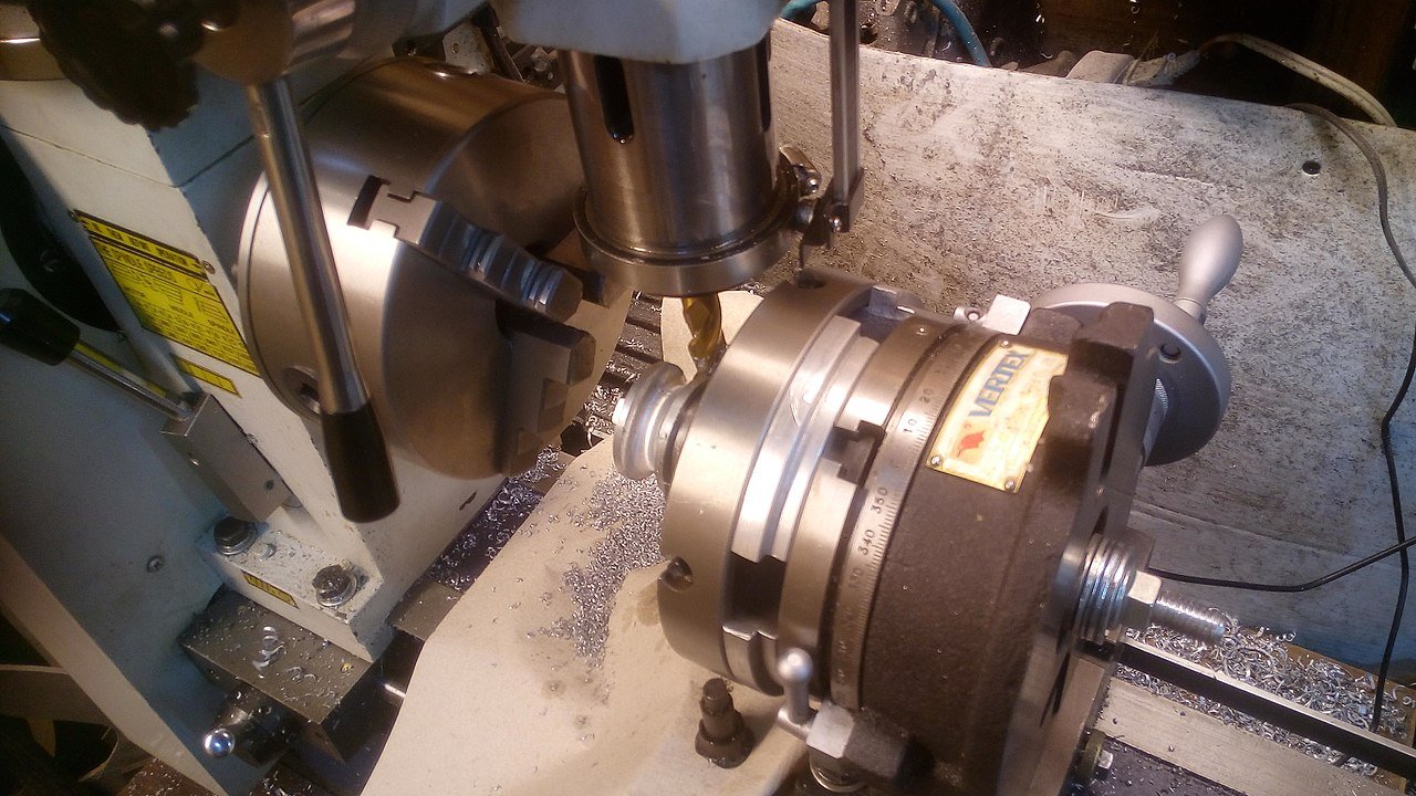
A 3-axis CNC machine can produce highly complex curved geometry.
The tool moves in X, Y, and Z while remaining in a fixed orientation relative to the machine.
For many molds, housings, plates, medical tools, and product components, this is completely sufficient.
The main limitation is accessibility.
The cutter must reach every machined area from the fixed spindle direction. If a surface turns underneath another feature, becomes nearly vertical, or requires machining from another side, the part may need to be repositioned.
Long tools may also be necessary to reach deep regions.
That creates additional challenges:
- greater tool deflection;
- more vibration;
- reduced finishing accuracy;
- collision risk between holder and workpiece;
- longer machining cycles.
The decision to use five-axis machining should therefore not be based simply on whether a part contains curves.
Many curved parts are best produced on three axes.
When 5-Axis Machining Improves Curved Surfaces
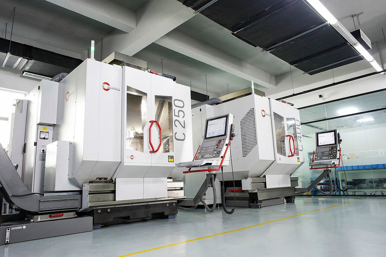
Five-axis machining becomes valuable when tool orientation itself can improve the process.
Instead of keeping the cutter vertical, the machine can tilt either the tool, the workpiece, or both.
This provides several advantages.
Better control of the ball nose contact point
Tilting the cutter slightly allows the machining process to avoid using the exact center of the ball nose.
The cutting edge can operate at a more favorable effective diameter, improving cutting action and surface quality.
Shorter tools
A five-axis machine can often tilt toward a deep or obstructed feature instead of relying on an extremely long tool.
Reducing tool overhang increases rigidity.
Better access
Undercuts, angled surfaces, impeller blades, and multi-face contours may become accessible without repeatedly repositioning the part.
Fewer setups
If several curved surfaces are located on different orientations, five-axis machining can reduce the number of times the component must be removed and re-clamped.
This is particularly important when geometric relationships between surfaces need to remain tightly controlled.
3-Axis vs 5-Axis for Curved Surface Machining
| Consideration | 3-Axis Milling | 5-Axis Milling |
|---|---|---|
| Simple curved surfaces | Excellent | Usually unnecessary |
| Shallow 3D contours | Excellent | Excellent |
| Deep complex cavities | Possible, often with long tools | Better access |
| Multi-face curved geometry | Multiple setups may be required | Often fewer setups |
| Tool orientation | Fixed | Continuously or positionally adjustable |
| Ball nose contact control | Limited | Better |
| Undercuts | Limited | Significantly improved |
| Programming complexity | Lower | Higher |
| Machine cost | Lower | Higher |
| Complex aerospace/impeller geometry | Limited | Strong advantage |
The most economical solution is the simplest machine configuration that can produce the required geometry and quality reliably.
Why Ball Nose Tools Can Leave Poor Finish on Shallow Surfaces
This is one of the most important issues in curved-surface machining.
A ball nose cutter does not have the same effective cutting speed across its entire radius.
At the outer portion of the cutter, the cutting edge travels through the material relatively quickly.
Toward the center, the effective diameter becomes smaller.
At the exact center, the surface speed approaches zero.
When a vertically oriented ball nose end mill finishes a nearly horizontal surface, the tool may contact the workpiece very close to this low-speed region.
Instead of cleanly forming a chip, the cutter can rub or smear the material.
This may produce:
- poor surface finish;
- heat;
- accelerated tool wear;
- visible streaking;
- inconsistent texture.
Possible solutions include tilting the tool on a 5-axis machine, changing tool geometry, modifying toolpath direction, or using a bull nose or circle-segment cutter where geometry allows.
Tool Orientation Matters in 5-Axis Finishing
In simultaneous 5-axis machining, tool orientation becomes another machining parameter.
The programmer can control lead and tilt angles so the cutter contacts the surface in a more favorable region.
Too little tilt may force cutting near the tool center.
Too much tilt can create other problems, including excessive engagement, reduced clearance, or unexpected scallop behavior.
Tool orientation also needs to change smoothly.
Abrupt changes in rotary-axis movement can create visible surface marks even when the cutter remains close to the nominal CAD geometry.
This is one reason high-quality five-axis finishing depends not only on CAM software but also on:
- machine kinematics;
- rotary-axis accuracy;
- control look-ahead;
- postprocessor quality;
- machine calibration.
How Material Affects Curved Surface Milling
The same curved geometry behaves differently when machined from aluminum, stainless steel, titanium, or engineering plastic.
Aluminum
Aluminum alloys such as 6061 and 7075 are common materials for curved housings, molds, aerospace components, robotics parts, and optical equipment.
Their relatively good machinability allows higher cutting speeds, but chip evacuation and built-up edge still require attention.
Long finishing cycles can also generate local heating, particularly on thin sections.
Sharp cutters and effective chip removal are important for maintaining a clean surface.
Stainless Steel
Stainless steel generally creates higher cutting forces and more heat than aluminum.
Long ball nose tools can deflect during contour finishing, particularly on deep features.
Tool wear may also cause gradual deterioration in surface quality over a long 3D machining cycle.
A finishing operation lasting several hours should therefore consider whether one tool can maintain the required edge condition throughout the entire surface.
Titanium
Titanium components frequently combine complex geometry with demanding dimensional requirements.
Heat concentration at the cutting edge, higher cutting forces, and tool wear make finishing strategy particularly important.
Stable engagement and appropriate coolant delivery are usually more important than aggressive material removal.
Five-axis machining can be particularly beneficial when it allows shorter, more rigid tools.
Engineering Plastics
PEEK, POM, nylon, PTFE, and similar materials introduce different challenges.
Cutting forces may be lower, but thermal expansion and local deformation can affect dimensions. Flexible plastic sections can also move under cutting pressure.
For precision curved plastic parts, sharp cutting edges and controlled heat are important.
Workholding Curved and Complex Parts
The workpiece must remain stable throughout machining without obstructing the surfaces that need to be cut.
This can be difficult when the finished component itself contains few flat clamping surfaces.
A common strategy is to design the process so that stable reference geometry remains available during the early operations.
The part may first be machined from one side while remaining attached to a larger block of stock. A second setup then uses machined datum surfaces, soft jaws, locating pins, or a custom fixture to hold the component while the remaining geometry is completed.
Depending on the application, workholding may include:
- custom soft jaws;
- machined nests;
- vacuum fixtures;
- modular fixturing;
- dovetail fixtures;
- sacrificial tabs;
- custom multi-axis fixtures.
Thin curved components require particular care. Excessive clamping force can distort the part, causing the finished surface to change shape after release.
Common Defects When Milling Curved Surfaces
Curved surfaces reveal machining problems very clearly because reflected light makes even small inconsistencies visible.
Scallop Marks
Regular ridges between adjacent passes usually indicate that stepover is too large relative to the cutter radius and required finish.
Reducing stepover is the simplest solution, although it increases machining time.
Step Marks
Step marks appear as visible bands or discontinuities rather than regular fine scallops.
They can result from several sources, including toolpath transitions, machine motion, tool-axis changes, surface-model discontinuities, and differences between adjacent machining regions.
This distinction matters because reducing stepover alone may not eliminate them.
Chatter
Repeating vibration patterns usually indicate insufficient rigidity somewhere in the machine-tool-fixture-workpiece system.
Long tool overhang is a common cause.
Witness Lines
When two finishing regions meet, a visible line may appear between them.
This can happen because the two toolpaths approach the surface differently or because the tool contact point changes at the boundary.
Gouging
Incorrect toolpath calculation, cutter compensation, tool definition, or 5-axis orientation can cause the cutter to remove material below the intended surface.
On high-value components, simulation and collision checking are therefore essential.
Uneven Gloss or Reflection
A surface may be dimensionally correct but show different optical appearance in different regions.
Changes in cutter direction, stepover, tool wear, or effective cutting speed can create variations that become obvious on polished or anodized parts.
How to Improve Surface Finish on Curved CNC Parts
Improving curved-surface finish usually requires several variables to work together.
1. Use a dedicated finishing tool
Do not use a heavily worn roughing cutter for the final surface.
A sharp, low-runout finishing tool provides much more consistent results.
2. Minimize tool overhang
Use the shortest cutter and holder combination that safely reaches the geometry.
For deep surfaces, consider several tool lengths rather than one long tool for the entire operation.
3. Leave consistent finishing stock
Semi-finish complicated surfaces so the final cutter removes a relatively uniform amount of material.
4. Match toolpath to surface slope
Use shallow-surface and steep-surface strategies where appropriate rather than one universal path.
5. Control stepover
Smaller stepover reduces scallop height, but use it intelligently. Extremely small spacing can add hours of machining time with little meaningful improvement if a later polishing operation is planned.
6. Keep finishing motion continuous
Smooth toolpaths with fewer abrupt reversals can reduce visible transition marks.
7. Manage tool wear
A long surface-finishing cycle can outlast the useful finishing condition of a small ball nose cutter.
If appearance or Ra is critical, tool-life planning may be necessary.
8. Use 5-axis tilt when it provides a real advantage
Avoiding the ball nose center and shortening tool reach can produce a much better finish on suitable geometry.
Curved Surface Machining and Thin-Wall Parts
A particularly difficult combination is a curved surface that is also thin.
Examples include aerospace skins, lightweight housings, robotic covers, medical-device components, and thin structural shells.
As material is removed, the component becomes less rigid. Cutting force can then push the surface away from the cutter.
The CAM system may command the tool to the correct location, but the physical workpiece moves during cutting.
Once the tool leaves, the surface springs back.
The result can include:
- contour error;
- inconsistent wall thickness;
- waviness;
- chatter;
- local overcut or undercut.
Possible strategies include staged material removal, temporary support geometry, symmetrical roughing, reduced finishing force, special fixtures, and leaving critical thin sections until later in the process.
This is an example of why machine positioning accuracy alone does not determine curved-surface accuracy.
How Curved Surfaces Are Inspected
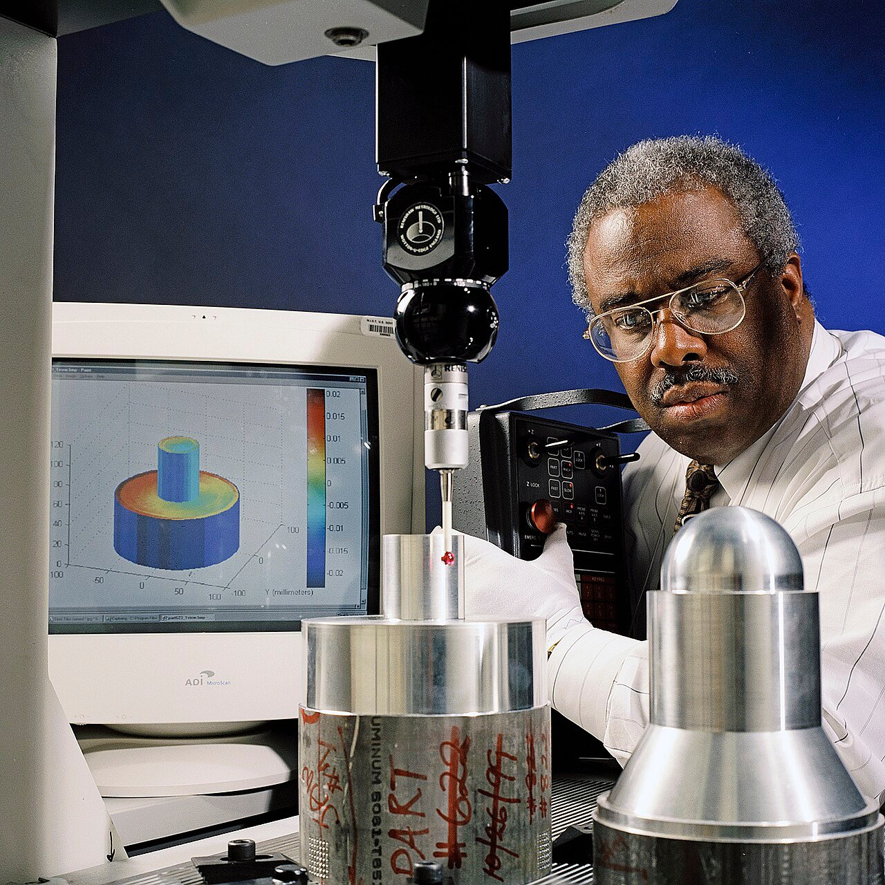
Inspection becomes more complex as geometry becomes less prismatic.
A few individual dimensions may be checked using conventional gauges or micrometers, but a complex 3D contour is usually evaluated relative to its nominal CAD geometry.
Depending on the component, inspection may use:
- CMM probing;
- CMM scanning;
- optical measurement;
- profile measurement;
- surface roughness measurement;
- dedicated checking fixtures.
For a precision housing, the curved exterior may mainly have a cosmetic requirement while the mounting surfaces and bores carry tighter dimensional tolerances.
For an impeller, mold insert, or optical component, the curved profile itself may be function-critical.
Inspection effort should therefore reflect how the surface influences part function.
Designing Curved Surfaces for Better CNC Machinability
Some curved components are unnecessarily difficult to manufacture because the CAD geometry was created without considering cutter access.
A few design decisions can make a significant difference.
Avoid extremely small concave radii where they are not functional
The cutting tool must be smaller than the internal curvature it needs to enter.
A very small concave radius may force the manufacturer to use a small, long, flexible ball nose cutter.
Increasing the radius slightly may allow a substantially more rigid tool.
Provide tool access
Deep surfaces surrounded by tall walls can force excessive tool overhang.
Opening the geometry where function allows can improve both finish and cycle time.
Maintain smooth surface continuity
Poorly constructed CAD surfaces containing small discontinuities can create undesirable machine motion or visible transitions.
High-quality surface geometry is especially important on cosmetic components and molds.
Identify which surfaces actually need premium finish
Requiring the same surface finish across hidden and visible regions can add considerable machine time.
Surface requirements should reflect function.
Example: Machining a Curved Aluminum Robotic Housing
Consider a 7075 aluminum robotic joint housing with a curved external form, internal pockets, bearing bores, cable openings, and several mounting faces.
A possible machining sequence might begin by face milling the raw stock to establish a stable datum. The internal pockets and large amounts of excess material would then be rough machined using flat or corner-radius end mills.
The curved exterior would initially remain oversized so that the part retains rigidity during heavy machining.
After most internal material has been removed, the external shape could be semi-finished to establish consistent stock.
A ball nose or suitable radius cutter would then finish the curved surfaces. Shallow regions might use a parallel or scallop strategy, while steeper regions use Z-level finishing.
If the component requires features on multiple orientations, 5-axis positioning could reduce additional setups and allow shorter tools.
Finally, the bearing bores and other critical interfaces would be finish machined and inspected relative to the established datums.
This sequence illustrates an important point: curved-surface machining rarely happens in isolation. It has to be integrated with the rest of the part’s functional geometry.
Example: Medical Instrument With an Ergonomic Freeform Surface
A handheld medical instrument may have a completely different manufacturing priority.
The curved grip surfaces could be designed primarily around ergonomics and cleanability, while internal pockets hold electronics or mechanical components.
For an early prototype, machining marks on hidden internal features may be acceptable, while the hand-contact surface needs a consistent cosmetic finish.
The manufacturer may therefore use faster roughing strategies internally and devote significantly more finishing time to the external contour.
A small ball nose cutter can finish detailed transitions around buttons and grip contours, while larger-radius tools handle broader surfaces.
If the final product will later be molded, the machined prototype also gives the engineering team an opportunity to evaluate the real physical curvature before committing to tooling.
When CNC Milling Is Better Than 3D Printing for Curved Parts
Additive manufacturing can produce highly complex freeform geometry, so it is reasonable to ask why curved surfaces should be CNC machined at all.
CNC milling remains particularly strong when the component requires:
- tight dimensional tolerances;
- high-strength wrought material;
- accurate mounting interfaces;
- precision bores;
- controlled flatness or perpendicularity;
- good surface finish;
- predictable material properties.
For example, a curved aluminum optical housing may contain a sculpted external form but also require precisely positioned lens interfaces and mounting surfaces.
Printing the geometry may be possible, but machining from wrought aluminum can provide more predictable material properties and tighter control of the functional interfaces.
In other situations, the two processes can be combined. A complex near-net shape can be additively manufactured and critical surfaces machined afterward.
When Grinding or Polishing Is Still Required
Milling is capable of producing very good surfaces, but there is a practical limit to how much machining time should be spent chasing extremely small tool marks.
If the required final surface is exceptionally smooth, a secondary process may be more economical.
Examples include:
- mold polishing;
- optical finishing;
- precision grinding;
- lapping;
- manual polishing.
The complete manufacturing plan should therefore consider the final required condition rather than optimizing milling in isolation.
A surface that will later be polished does not need the same finishing strategy as one that will remain as-machined.
Curved Surface Milling Checklist
| Area | Main question |
|---|---|
| Surface geometry | Is the surface shallow, steep, concave, convex, or freeform? |
| Tool access | Can the cutter and holder reach all regions without collision? |
| Machine configuration | Is 3-axis sufficient, or does 5-axis orientation improve access? |
| Roughing | Can most material be removed with a rigid, productive cutter? |
| Semi-finishing | Is finishing stock consistent across the entire contour? |
| Finishing tool | Ball nose, bull nose, or circle-segment cutter? |
| Toolpath | Parallel, Z-level, scallop, spiral, pencil, or combination? |
| Stepover | Does it meet the required scallop height and surface quality? |
| Tool orientation | Is the cutter contacting the surface in an effective region? |
| Rigidity | Are tool overhang, fixture, and workpiece stiffness sufficient? |
| Surface requirement | Cosmetic, functional, specified Ra, or secondary polished? |
| Inspection | How will the actual 3D profile be verified? |
How 6CNC Approaches Complex Curved-Surface Machining
At 6CNC, curved-surface components are reviewed as complete machining processes rather than simply assigning a ball nose finishing toolpath to a 3D model.
The manufacturing plan can consider how the part should be rough machined, which geometry needs to remain for support, where semi-finishing is necessary, how tool length changes across the part, and whether a 3-axis or 5-axis strategy provides the most stable result.
Depending on the component, the process can include CNC milling, 5-axis machining, turning, mill-turn machining, precision grinding, Wire EDM, and other supporting manufacturing processes.
For complex surfaces, inspection can also be planned around the actual functional requirement. CMM, optical measurement, surface roughness testing, and conventional dimensional inspection may be combined depending on whether the curved geometry itself is critical or whether the tighter requirements are concentrated around bores, mounting faces, and other interfaces.
This becomes particularly important when a component moves from a prototype into small-batch production. The first part may demonstrate that the geometry can be machined, but the tooling, fixturing, finishing strategy, and inspection method also need to remain stable across the full batch.
Final Thoughts
CNC milling curved surfaces is not simply a matter of replacing a flat end mill with a ball nose cutter.
The final result depends on the interaction between surface geometry, cutter shape, tool contact point, toolpath direction, stepover, tool rigidity, machine motion, workholding, and inspection.
For relatively simple curved geometry, a well-planned 3-axis process may provide excellent results. As surfaces become deeper, more obstructed, multi-directional, or sensitive to tool orientation, 5-axis machining can provide important advantages by shortening tools and improving cutter contact.
The best results usually come from separating the process into logical stages: remove material efficiently during roughing, create consistent stock during semi-finishing, select finishing strategies according to surface slope, and verify the critical geometry using an appropriate inspection method.
Most importantly, the machining strategy should match the function of the part. A cosmetic product housing, an aerospace contour, a robotic joint, a medical instrument, and a precision mold may all contain curved surfaces, but they do not necessarily need the same tools, tolerances, finishing cycle, or inspection plan.
If you are developing a component with complex curved geometry, deep contours, thin walls, multi-axis features, or demanding surface requirements, 6CNC supports precision CNC machining from prototype through small-batch production.
Send your CAD files, engineering drawings, material requirements, and expected quantities to 6CNC for manufacturing review and quotation.
Frequently Asked Questions
Can a 3-axis CNC machine mill curved surfaces?
Yes. A 3-axis CNC machine can produce highly complex curved surfaces as long as the geometry is accessible from the fixed tool orientation. Molds, curved housings, and many freeform components are routinely produced using 3-axis contour milling.
Do curved surfaces require 5-axis CNC machining?
No. Five-axis machining becomes useful when the surface requires multiple tool orientations, deep access, shorter tool reach, undercut machining, or better control of the cutter contact point. Many curved parts can be produced more economically using three axes.
What cutting tool is best for curved surfaces?
Ball nose end mills are among the most common tools because their rounded profile follows complex contours effectively. Bull nose and circle-segment cutters may be more productive on suitable shallow or steep regions.
Why are ball nose end mills used for curved surfaces?
The rounded end allows the cutter to contact surfaces at different slopes without leaving a sharp cutter-corner profile. This makes ball nose tools particularly useful for molds, concave geometry, convex contours, and freeform surfaces.
What is stepover in curved surface milling?
Stepover is the lateral spacing between adjacent tool passes. A larger stepover generally leaves larger scallops and reduces machining time, while a smaller stepover produces a smoother surface but requires more tool passes.
What causes visible lines on a CNC-milled curved surface?
Visible lines can result from excessive scallop height, toolpath transitions, cutter wear, machine motion, vibration, changes in tool orientation, runout, or discontinuities between machining regions.
Why does a ball nose cutter sometimes leave a poor finish on a shallow surface?
When the tool is vertical, a shallow surface may be cut close to the center of the ball nose, where effective cutting speed is very low. Five-axis tilt or an alternative cutter geometry can move the contact point into a more effective cutting region.
What is the difference between parallel and Z-level finishing?
Parallel finishing uses closely spaced passes across the surface and generally works well on shallow geometry. Z-level finishing follows contours at successive heights and is normally more effective on steep walls. Complex parts often combine both.
How do you reduce scallop marks on a curved surface?
Common methods include reducing stepover, increasing effective cutter radius, selecting a better toolpath, using circle-segment cutters where appropriate, or performing secondary finishing.
How are complex CNC curved surfaces inspected?
Depending on accuracy requirements, curved surfaces can be inspected using CMM probing or scanning, optical measurement, profile measurement, CAD comparison, and surface roughness testing.
Is CNC machining or 3D printing better for curved parts?
It depends on the requirement. 3D printing provides excellent geometric freedom, while CNC machining is generally stronger for tight tolerances, machined interfaces, surface quality, and components requiring wrought engineering materials. Some parts benefit from combining both processes.