Deep pockets often look simple in CAD: remove material until the floor reaches the required depth. On the machine, the same feature may demand a long-reach cutter, conservative passes and careful chip evacuation. A pocket that is only a few millimeters deeper can change the entire process plan.
The real constraint is not depth alone. It is depth relative to tool diameter, pocket width, corner radius, material and finish requirement. This guide explains how those factors interact and what engineers can change before the geometry becomes an expensive machining problem.
Why deep pockets become unstable
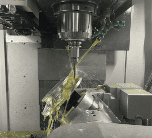
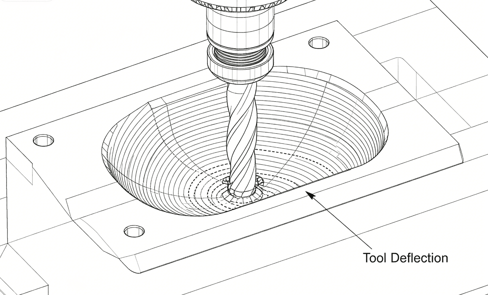
Cutting force bends both the tool and the workpiece. A short tool behaves like a stiff beam. A long tool behaves like a flexible lever, so the same cutting load produces more deflection at the tip. This may leave tapered walls, chatter marks or material that must be removed with repeated finishing passes.
Toolholders and the spindle nose also need clearance. A CAD opening may be wide enough for the cutter but too narrow for the holder at full depth. When access is limited, the process may need a reduced-neck tool, a smaller diameter or another machining orientation.
Chips create a second problem. Recutting trapped chips damages the finish and adds heat. Deep cavities in aluminum may pack with long chips, while tough stainless materials increase heat and tool wear. Coolant delivery and evacuation space must be considered together.
Design changes with the largest impact
Increase the pocket opening if the assembly permits it. A wider opening allows a larger tool and better holder clearance. Increase internal corner radii for the same reason. If only one local area needs extra depth, use a stepped pocket instead of extending the deepest floor across the entire cavity.
Avoid requiring the same finish and profile tolerance over every wall and the full floor. Mark the functional contact areas. A critical sealing shelf may need a controlled finish, while a clearance wall may not.
Where a deep vertical wall is unavoidable, consider whether the part can be split and assembled, approached from a second side or machined from near-net material. The right answer depends on loads, sealing and production volume, but the comparison should happen before release.
A practical machining sequence
A stable process normally separates roughing from finishing. Roughing removes most material with a rigid tool and leaves controlled stock. Semi-finishing makes the remaining stock more uniform. Finishing then uses a predictable engagement to bring the wall and floor to size.
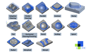
Adaptive or constant-engagement paths can reduce sudden load changes in roughing. Step-down and step-over values must match the tool, material and coolant strategy. One aggressive full-depth pass is rarely the fastest route if it causes tool failure or another finishing cycle.
The finishing tool should extend only as far as necessary. Separate tools may be justified for upper and lower regions so the entire pocket is not machined with the least rigid option.
How deep pockets should be inspected
Inspection access can be harder than cutting access. Standard calipers may verify the opening but not wall taper, corner condition or the true floor position relative to datums. A CMM probe, depth gauge, bore gauge or optical method may be needed depending on geometry.
Define whether the pocket floor, walls or both are critical. If a thin floor can flex, state the intended measurement condition. Inspection requirements should be agreed before machining because probe access may influence feature design.
Deep pocket risk review
| Design condition | Likely effect | Possible response |
|---|---|---|
| High depth-to-width ratio | Long tool and reduced rigidity | Widen access or use stepped depths |
| Small corner radius | Smaller cutter and longer cycle | Increase radius or add corner relief |
| Thin pocket walls | Deflection and thickness variation | Leave support and finish symmetrically |
| Closed cavity | Poor chip evacuation | Add access or plan coolant and air evacuation |
| Tight floor-to-datum depth | More finishing and inspection | Identify the functional area and method |
| Fine finish at full depth | Long-reach finishing risk | Specify finish only where required |
Quantify the real constraint: effective overhang
Pocket depth is not the same as tool overhang. The cutting edge must reach the deepest surface, while the neck, shank, holder and spindle nose must clear the upper walls. The effective unsupported length may therefore exceed the modeled depth. Draft angles, islands and nearby bosses can make holder clearance the limiting geometry.
A first-pass review should calculate depth divided by cutter diameter, but it should not treat one ratio as a universal acceptance limit. A 6:1 reach in aluminum with light radial engagement is different from a 6:1 full-width cut in hardened steel. The ratio flags risk; tool construction, material and engagement determine the response.
Why reach dominates deflection
Using the simplified cantilever relationship δ ∝ FL³/d⁴, increasing unsupported length from 30 to 45 mm multiplies the L³ term by 3.375. Under an otherwise identical load, a 45 mm reach can deflect more than three times as much as a 30 mm reach. Increasing diameter from 6 to 8 mm multiplies the d⁴ stiffness term by about 3.16.
This is why widening a pocket or increasing an internal radius can transform the process. It permits a larger cutter, a shorter neck or both. The improvement is not linear; small geometric changes can produce large stiffness gains.
Worked example: 45 mm pocket with R3 corners
Assume a closed 45 mm-deep pocket has R3 vertical corners. A 6 mm end mill can theoretically match that radius, but using the same tool for full-depth roughing and corner finishing creates two problems. It needs enough flute or neck length to reach the floor, and it reaches maximum engagement as it enters a matching-radius corner.
A more stable plan uses a larger tool for upper and bulk roughing, leaves controlled radial and axial stock, then uses rest machining to identify only the material the larger tool could not reach. A reduced-neck 6 mm tool finishes the lower wall and corner in light engagement. If the drawing accepts R4, an 8 mm-class tool may become possible, and stiffness improves sharply.
Separate roughing, semi-finishing and finishing stock
Roughing should create a predictable remainder rather than chase final geometry. Constant-engagement strategies reduce sudden load changes, while helical or ramp entry avoids forcing a non-center-cutting tool straight into solid stock. Autodesk notes that sharp internal turns can bury the cutter, cause chatter and distort finish; a minimum cutting radius smooths the path but leaves stock for a later operation.
Semi-finishing matters when roughing leaves uneven stock. A finishing tool deflects according to load. If one region has 0.1 mm stock and another has 0.8 mm, the wall will not respond uniformly. A semi-finish pass normalizes the allowance so the final pass removes a consistent amount.
Chip evacuation is part of the geometry
A closed pocket gives chips only one main exit: upward. Deep cavities reduce coolant access and allow chips to circulate back into the cut. Aluminum can form long chips that pack around the tool. Stainless steel concentrates heat near the cutting edge. Recut chips increase edge damage, floor scratching and the chance of built-up edge.
Design options include an open side, a larger access window, a through-hole that also supports evacuation or a staged floor. Process options include through-tool coolant, directed air, pecking between levels and toolpaths that avoid pushing chips into a dead corner. The correct choice depends on material and safety controls.
Inspect depth, taper and corner condition separately
A single depth measurement does not prove the pocket. Wall taper requires measurements at more than one height. Floor flatness is distinct from depth relative to datum A. Corner radius and remaining stock may need optical inspection or a CMM path with a suitable stylus.
For a flexible floor, the drawing and inspection plan should define the supported state. A thin membrane measured while clamped may not have the same shape after release. If free-state behavior is functional, measure it in that condition.
Technical references
- Autodesk Minimum Cutting Radius reference
- Autodesk 3D Offset Roughing reference
- Sandvik Coromant Milling Tools selection guide
What to send with your RFQ
- Pocket depth, width and smallest corner radius
- Wall and floor thickness
- Critical wall, floor and datum relationships
- Required surface roughness by area
- Material grade and heat-treatment condition
- Open sides or alternate tool access
- Expected inspection method and report
A useful RFQ gives the manufacturing team enough information to separate functional requirements from preferences. If a feature is difficult to reach or inspect, a short engineering review before release can prevent a costly revision later.
Review the part before production
Send 6CNC your CAD model, drawing, material and quantity. Our team will review machining access, setups, critical tolerances and inspection needs before quoting.
Frequently asked questions
What is considered a deep pocket in CNC milling?
There is no single depth threshold. A pocket becomes deep when tool reach and clearance reduce rigidity; the depth-to-tool-diameter relationship is more useful than depth alone.
Why do deep pocket walls taper?
Tool deflection, workpiece movement, uneven stock and thermal effects can all make the upper and lower wall dimensions differ.
Does a smaller tool solve deep-pocket access?
It may improve geometric access, but it usually reduces rigidity and increases cycle time. Holder clearance and corner requirements should be reviewed first.
Can five-axis machining help with deep pockets?
It can improve tool orientation and shorten effective reach for some open geometry, but it does not remove access limits in a narrow closed cavity.
Plan the process around the functional features
Good CNC machining starts with a clear definition of what the part must do. Tool access, rigidity, datums and inspection should support that function. For additional process options, see our CNC milling services, 5-axis machining and quality assurance resources.

![Comparison of Operating Principles: This figure illustrates a microscopic comparison of the surface waviness and residual scallop height generated by a face milling cutter and a ball-nose cutter under different stepover and step-down settings. [Figure 4-1]](https://6-cnc.com/wp-content/uploads/2026/06/image-2-300x199.png)