A part can be easy to model and difficult to machine. Deep pockets force long tools. Thin walls move under cutting pressure. Small internal radii increase tool changes and cycle time. A design may still be machinable, but the quote becomes higher and the process less predictable.
This CNC milling design guide focuses on the decisions that affect accuracy, cost and repeatability before a drawing reaches the shop. The goal is not to remove useful features. It is to make each feature intentional and give the machinist enough access, support and inspection information to produce it consistently.
For most projects, the biggest gains come from four areas: keeping walls supportable, limiting pocket depth, using realistic corner radii and planning datums around the required setups.
Start with tool access and part orientation
A milling cutter approaches the workpiece along a limited set of directions. Every new direction may require indexing, a new fixture or another machine setup. Before adding detail, ask whether the feature can be reached from the top, side or an angled orientation without another clamping operation.
Fewer setups do more than reduce labor. They also reduce datum-transfer error. Features machined in one clamping maintain their relationship more reliably than features measured, unclamped and relocated for a second operation. If two bores require close positional control, orienting them for one setup can be more valuable than applying a tighter tolerance after the fact.
Provide clear primary, secondary and tertiary datums on the drawing. Choose stable surfaces that can be located and inspected. A small cosmetic face or flexible wall is rarely a good primary datum.
Design walls that remain stable
Thin walls can deflect away from the cutter and spring back after the pass. The result may be taper, waviness or a thickness that changes with measurement pressure. Aluminum often permits thinner walls than steel or engineering plastics, but geometry, height, unsupported length and tolerance matter as much as material.
Add ribs or local support where the design allows it. Keep wall thickness consistent to reduce uneven stress release. When a wall must be thin, identify which face and thickness are functional so the process plan can leave support material until the final passes.
Do not define every wall with the same tight profile tolerance. A sealing land, bearing seat and cosmetic cover do different jobs and should not carry identical controls.
Keep pocket depth and corner radius connected
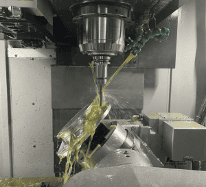
Pocket depth determines tool reach. As the cutter extends farther from the holder, rigidity falls and vibration risk rises. A deep narrow pocket may require reduced cutting parameters, step-down machining and several finishing passes. It can also trap chips and heat.
Internal vertical corners cannot be perfectly sharp with a rotating end mill. The cutter radius always remains in the corner. A larger specified radius allows a larger, stiffer tool and usually improves surface consistency. A useful design practice is to make the corner radius slightly larger than a standard cutter radius so the tool does not remain fully engaged through the turn.
If a mating rectangular part requires corner clearance, consider a relief feature or dog-bone corner instead of forcing a very small radius through the full depth.
Apply tolerances according to function
General dimensions, locating features and critical interfaces should not all use one tolerance. Tight limits may require slower finishing passes, controlled temperature, dedicated gauges or CMM inspection. They also reduce the process window for no functional benefit when applied everywhere.
Identify bearing bores, dowel holes, sealing faces and assembly interfaces as critical-to-quality features. Use general tolerances for non-critical geometry. If surface roughness matters, state it separately from dimensional size because a part can meet size and still have an unsuitable contact surface.
The drawing should also state the required edge condition. Terms such as break sharp edges need an agreed range when edge size affects assembly, coating or safety.
CNC milling design review table
| Feature | Lower-risk direction | Why it helps |
|---|---|---|
| Internal corner | Use the largest functional radius | Allows a stiffer cutter and smoother tool motion |
| Deep pocket | Increase width or reduce depth where possible | Improves reach, chip evacuation and stability |
| Thin wall | Add support or keep thickness consistent | Reduces deflection and stress-related movement |
| Hole pattern | Reference functional datums | Makes machining and inspection agree |
| Tight tolerance | Limit it to functional features | Reduces cycle time and inspection cost |
| Multi-side geometry | Group related features in one orientation | Reduces setup and datum-transfer error |
Use machining equations as a design check
Three relationships explain many milling problems before CAM programming begins. Spindle speed is calculated from cutting speed and tool diameter:
n = spindle speed in rpm, Vc = cutting speed in m/min, D = cutter diameter in mm.
Programmed table feed is then estimated from spindle speed, flute count and feed per tooth:
Vf = table feed in mm/min, z = effective cutting edges, fz = feed per tooth in mm.
These formulas do not set the final process by themselves. Tool engagement, holder rigidity, material, coolant and machine dynamics still matter. They do show why a feature that forces the cutter diameter from 12 mm down to 4 mm is not a cosmetic CAD change. The smaller tool needs a different rpm range, carries a smaller core and may require more passes.
Tool stiffness changes much faster than diameter
For a simplified cantilever model, tip deflection follows δ = FL³/(3EI). For a round tool, the second moment of area is I = πd⁴/64. The useful design lesson is the scaling: deflection grows with the cube of unsupported length and falls with the fourth power of diameter.
If the same cutting load and material are assumed, doubling tool overhang can increase idealized deflection eightfold. Moving from a 6 mm to an 8 mm diameter tool increases the d⁴ stiffness term by about 3.16 times. Real cutters, holders and spindles are more complex than this model, but the direction is decisive: a little more corner radius or access width can create a much stiffer process.
Worked example: a milled electronics housing
Consider a 6061 aluminum housing with a 48 × 32 mm internal cavity, 28 mm depth, 2 mm walls and R2 internal corners. The R2 corners cap the conventional end-mill diameter at 4 mm if the tool must finish the full corner. That tool must also reach below the 28 mm wall. The combination of small diameter, long reach and a flexible wall makes a one-tool strategy vulnerable to chatter and wall taper.
A stronger process separates the jobs. A larger tool roughs the open cavity and leaves uniform stock. A medium tool finishes most walls. A small tool removes only the rest material in the corners. If the designer can change the corner from R2 to R4, the finishing tool can become substantially stiffer. If the mating PCB or insert only needs clearance, local corner relief may remove the need for the small tool entirely.
The drawing should not apply the same profile tolerance to all four walls. It can control the connector face and locating bosses tightly while leaving clearance walls under a general tolerance. This focuses machining and CMM time on the features that affect assembly.
Match the datum system to the machining sequence
A functional datum should be large and stable enough to locate the part. For a housing, the mounting face may be datum A, a locating edge datum B and a dowel feature datum C. Hole position and connector geometry can then reference A|B|C. If the machinist can reproduce that datum structure in the fixture, manufacturing and inspection use the same coordinate logic.
A datum on a thin unfinished wall creates ambiguity because clamping and probing can move it. A datum hidden after the first operation forces a transfer. When the functional datum cannot be held directly, the engineering review should define surrogate features and how their relationship will be verified.
Calculate cost from operations, not part volume
Material removal rate is often approximated as Q = ap × ae × Vf, where ap is axial depth, ae is radial width and Vf is table feed. But high Q does not guarantee the lowest part cost. Tool changes, probing, repositioning, deburring and inspection can dominate a low-volume job.
A useful DFM review therefore counts orientations, unique tools, deep-reach tools, controlled surfaces and inspection setups. Removing one unnecessary orientation may save more than reducing the raw stock by 10%. Standardizing radii may remove two tool changes. Relaxing a non-functional profile tolerance may remove a CMM program and an extra finishing pass.
Technical references
What to send with your RFQ
- STEP or Parasolid model plus a controlled PDF drawing
- Material grade and any required condition or temper
- Critical dimensions and functional datums
- Threads, inserts and edge-break requirements
- Surface finish or coating with masked areas identified
- Inspection report and sampling requirements
- Expected prototype and production quantities
A useful RFQ gives the manufacturing team enough information to separate functional requirements from preferences. If a feature is difficult to reach or inspect, a short engineering review before release can prevent a costly revision later.
Review the part before production
Send 6CNC your CAD model, drawing, material and quantity. Our team will review machining access, setups, critical tolerances and inspection needs before quoting.
Frequently asked questions
What makes a CNC milled part expensive?
Multiple setups, deep narrow pockets, small internal radii, extensive tight tolerances and difficult inspection access are common cost drivers.
Can CNC milling make a sharp internal corner?
A rotating cutter leaves an internal radius. EDM, broaching or a relief feature may be considered when a functional sharp corner is unavoidable.
Should the CAD model or drawing control the part?
State the controlling document in the RFQ. The model defines geometry well, while the drawing should define tolerances, datums, finishes and inspection notes.
When should I request a DFM review?
Request one before design release when the part includes deep pockets, thin walls, multi-axis features or tight relationships between datums.
Plan the process around the functional features
Good CNC machining starts with a clear definition of what the part must do. Tool access, rigidity, datums and inspection should support that function. For additional process options, see our CNC milling services, 5-axis machining and quality assurance resources.

![Comparison of Operating Principles: This figure illustrates a microscopic comparison of the surface waviness and residual scallop height generated by a face milling cutter and a ball-nose cutter under different stepover and step-down settings. [Figure 4-1]](https://6-cnc.com/wp-content/uploads/2026/06/image-2-300x199.png)