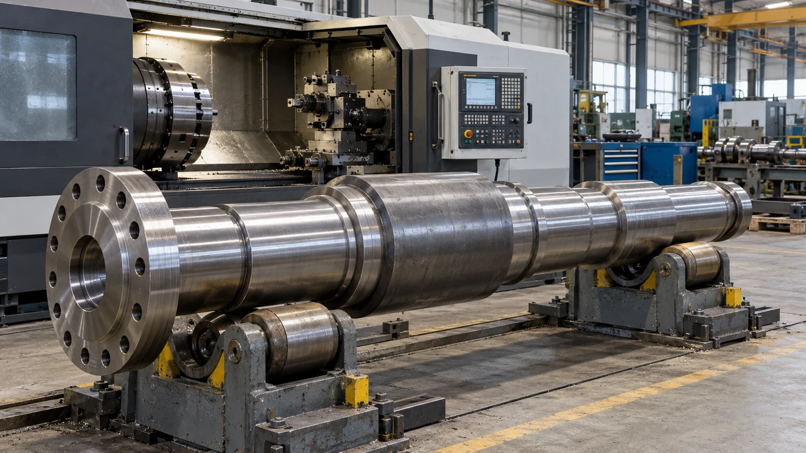
A shaft can be perfectly turned on a CNC lathe and still require another operation before it is ready for a bearing, seal, bushing, or precision assembly.
The diameter may be slightly oversized. The surface may contain turning marks. Roundness may not be sufficient. Long, slender parts may also be difficult to grind accurately between centers because they can deflect under cutting forces.
This is where centerless grinding becomes valuable.
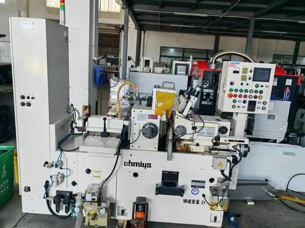
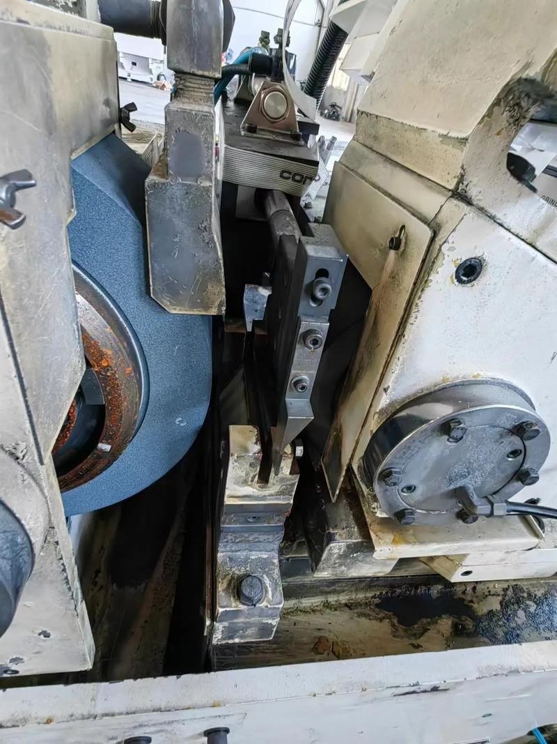
Unlike conventional cylindrical grinding, centerless grinding does not hold the workpiece between centers or in a chuck. Instead, the part is supported between a grinding wheel, a regulating wheel, and a work-rest blade.
This seemingly simple difference makes the process especially effective for producing accurate cylindrical parts in high volumes.
Modern centerless grinding services are widely used to manufacture:
- Precision shafts
- Pins
- Dowels
- Piston rods
- Valve components
- Bearing components
- Bushings
- Tubes
- Medical components
- Automotive parts
- Aerospace components
The process can deliver consistent diameters, improved roundness, and fine surface finishes while also supporting efficient production.
However, centerless grinding is not suitable for every cylindrical part.
Understanding the difference between through-feed grinding, infeed centerless grinding, and conventional cylindrical grinding is essential when selecting the correct manufacturing process.
This guide explains how centerless grinding works, what types of parts it can produce, what accuracy can realistically be expected, and what engineers should consider when designing parts for centerless grinding.
What Is Centerless Grinding?
Centerless grinding is an abrasive machining process used to remove material from the outside diameter of a cylindrical workpiece.
Unlike conventional cylindrical grinding, the workpiece is not held between centers.
Instead, the part is supported at three contact points:
- The grinding wheel
- The regulating wheel
- The work-rest blade
The grinding wheel rotates at relatively high speed and removes material from the part.
The regulating wheel rotates at a much lower speed and controls the rotational speed and axial movement of the workpiece.
The work-rest blade supports the part vertically between the two wheels.
Because the workpiece does not require a chuck, center hole, or other dedicated holding feature, centerless grinding can process many cylindrical components continuously and efficiently.
This makes precision centerless grinding especially attractive for parts that require:
- Consistent outside diameters
- Tight diameter control
- Good roundness
- Fine surface finishes
- High-volume production
- Long cylindrical grinding lengths
How Does Centerless Grinding Work?
The basic centerless grinding setup consists of two wheels positioned opposite each other with the workpiece between them.
The workpiece rests on the work-rest blade.
Grinding Wheel
The grinding wheel performs the cutting.
Its abrasive grains remove a very small amount of material as the workpiece rotates against the wheel.
Grinding wheels can be selected according to:
- Workpiece material
- Hardness
- Stock removal
- Diameter
- Required surface finish
- Production rate
Wheel diameter, abrasive material, grit size, bond type, and hardness all affect grinding performance.
Regulating Wheel
The regulating wheel does not perform the primary material removal.
Instead, it controls:
- Workpiece rotation
- Feed rate
- Axial movement
- Grinding stability
In through-feed grinding, the regulating wheel is tilted slightly relative to the grinding wheel.
This generates an axial force that moves the workpiece through the machine.
Work-Rest Blade
The work-rest blade supports the workpiece between the grinding and regulating wheels.
The height and angle of this blade are extremely important.
Changing the workpiece centerline relative to the wheel centers affects:
- Roundness
- Stability
- Grinding behavior
- Part geometry
Proper machine setup is therefore one of the most important factors in successful centerless shaft grinding.
Why Is Centerless Grinding Different From Cylindrical Grinding?
The defining feature of centerless grinding is that the part does not need to be mechanically clamped.
In conventional cylindrical grinding, the part is typically held:
- Between centers
- In a chuck
- In a collet
The machine rotates the workpiece around a mechanically established axis.
Centerless grinding works differently.
The part finds its rotational position dynamically between the grinding wheel, regulating wheel, and support blade.
This allows manufacturers to grind parts that would otherwise be difficult or time-consuming to fixture.
It is particularly useful for:
- Small-diameter shafts
- Long slender shafts
- Pins
- Rods
- High-volume cylindrical components
For suitable geometry, the absence of individual part fixturing can significantly increase productivity.
Three Main Types of Centerless Grinding
Centerless grinding is normally divided into three process types:
- Through-feed grinding
- Infeed grinding
- End-feed grinding
The first two are the most common.
Through-Feed Centerless Grinding
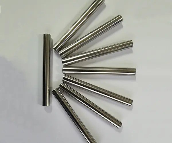
Through-feed grinding is one of the most productive forms of centerless grinding.
The workpiece enters one side of the machine and continuously travels between the grinding and regulating wheels until it exits the opposite side.
There is normally no need to stop the machine and individually load or unload each component during the grinding cycle.
This makes through-feed grinding highly suitable for long production runs.
How Through-Feed Grinding Works
The regulating wheel is positioned at a slight angle.
As it rotates, this angle produces an axial feeding force.
The workpiece therefore:
- Rotates
- Moves forward
- Contacts the grinding wheel
- Gradually reaches its final diameter
Several parts can follow one another through the grinding zone.
Best Parts for Through-Feed Grinding
Through-feed centerless grinding works best when the outside diameter being ground is continuous.
Typical parts include:
- Straight shafts
- Rods
- Pins
- Dowels
- Tubes
- Bearing rollers
- Straight cylindrical components
A part that can pass completely through the grinding zone without being obstructed by a larger shoulder is generally a good candidate.
Advantages of Through-Feed Grinding
Through-feed grinding offers several manufacturing advantages.
High Production Rate
Parts can move continuously through the machine.
This reduces handling time and makes the method suitable for production quantities.
No Individual Clamping
Because parts do not require individual chucking or centering, loading time is reduced.
Excellent for Long Cylindrical Parts
Long rods and shafts can often be processed efficiently.
Good Dimensional Consistency
Once the grinding process is correctly established, large quantities of parts can be produced with consistent diameters.
Infeed Centerless Grinding
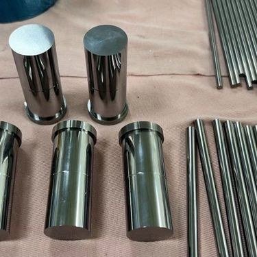
Infeed centerless grinding, also called plunge grinding, is used when a workpiece cannot pass completely through the machine.
Instead of moving continuously through the wheels, the component is placed into the grinding zone and the grinding wheel moves radially into the part.
This makes infeed centerless grinding suitable for parts with more complex outside profiles.
Typical examples include:
- Stepped shafts
- Parts with shoulders
- Components with multiple diameters
- Headed pins
- Profiled cylindrical parts
How Infeed Grinding Works
The part is loaded into a defined position between the grinding and regulating wheels.
The grinding wheel profile is dressed to match the required component geometry.
The wheel then moves into the workpiece until the required shape and diameter are achieved.
After grinding, the part is removed and the next component is loaded.
Unlike through-feed grinding, the workpiece does not continuously pass through the machine.
When Should You Use Infeed Grinding?
Use infeed centerless grinding when:
- A shoulder prevents the part from passing through the machine
- Several diameters must be ground simultaneously
- A specific external profile is required
- The part contains stepped geometry
- The grinding section is limited to a defined axial area
The tradeoff is that infeed grinding normally involves more complex setup than through-feed grinding.
End-Feed Centerless Grinding
End-feed grinding is less commonly discussed but is useful for certain tapered components.
The workpiece enters the grinding zone axially until it reaches a mechanical stop.
The grinding and regulating wheels are dressed to create the required profile.
This process can be used for:
- Tapered shafts
- Components with controlled end geometry
- Certain headed cylindrical parts
After the grinding cycle, the part is withdrawn from the same side from which it entered.
Through-Feed vs. Infeed Centerless Grinding
Choosing the correct centerless grinding method depends mainly on part geometry.
| Feature | Through-Feed Grinding | Infeed Grinding |
|---|---|---|
| Workpiece movement | Continuously through wheels | Remains in grinding zone |
| Best geometry | Straight, continuous OD | Stepped or profiled OD |
| Shoulders allowed | Generally no | Yes |
| Production speed | Very high | Moderate |
| Wheel profile | Typically straight | May be profile-dressed |
| Typical parts | Rods, pins, straight shafts | Stepped shafts, headed pins |
| Automation potential | Excellent | Excellent |
| Setup complexity | Lower | Higher |
For a simple straight shaft, through feed grinding will often be the more economical choice.
For a stepped shaft, infeed centerless grinding may be necessary.
What Accuracy Can Centerless Grinding Achieve?
Centerless grinding is used specifically because it can produce highly controlled outside diameters.
However, there is no single tolerance that applies to every centerless-ground part.
Achievable accuracy depends on:
- Part diameter
- Grinding length
- Material
- Hardness
- Initial stock condition
- Part geometry
- Wheel specification
- Grinding machine
- Process stability
- Production quantity
- Inspection method
Under controlled conditions, centerless grinding can support micron-level dimensional control on suitable components.
But drawing requirements should be evaluated individually rather than assuming that every shaft can hold the same tolerance.
Long, flexible parts and very thin components behave differently from short, rigid parts.
What Does Precision Centerless Grinding Improve?
Centerless grinding is not simply used to reduce diameter.
The process can improve several characteristics simultaneously.
Diameter
The most obvious function is bringing the outside diameter to its required final size.
This is important for:
- Bearing fits
- Bushings
- Seals
- Sliding assemblies
- Press fits
Roundness
Turning operations may leave small roundness errors.
Properly controlled centerless grinding can improve the circular form of the finished component.
Surface Finish
Grinding removes turning marks and produces a finer surface.
This can be important where the shaft contacts:
- Bearings
- Seals
- Bushings
- Sliding components
Size Consistency
Centerless grinding is particularly useful when hundreds or thousands of parts must remain within a tightly controlled diameter range.
Once the process is stable, it can deliver strong part-to-part consistency.
Centerless Shaft Grinding
Centerless shaft grinding is widely used for precision cylindrical shafts.
A turned shaft may already be close to final dimensions, but grinding can be added when its functional surfaces require greater control.
Typical examples include:
- Motor shafts
- Transmission shafts
- Hydraulic rods
- Valve stems
- Pump shafts
- Guide shafts
- Precision pins
- Actuator shafts
- Bearing journals
The grinding operation may be applied to the entire shaft or only selected functional diameters.
Why Grind a Shaft After CNC Turning?
Modern CNC lathes can produce highly accurate shafts.
So why add grinding?
Because turning and grinding solve different manufacturing problems.
Turning is excellent for producing:
- Overall geometry
- Threads
- Grooves
- Shoulders
- Tapers
- Complex profiles
Grinding becomes valuable when certain external surfaces require tighter control.
For example, a shaft might contain:
- Threaded section
- Retaining-ring groove
- Shoulder
- Bearing diameter
- Seal diameter
Most of the shaft can be CNC turned.
Only the bearing and sealing diameters may require final grinding.
This approach balances precision and manufacturing cost.
Typical Parts Made With Centerless Grinding
Centerless grinding is widely used across manufacturing industries.
Common components include:
Precision Pins
Examples include:
- Dowel pins
- Locating pins
- Guide pins
- Pivot pins
These often require highly consistent outside diameters.
Shafts
Examples include:
- Motor shafts
- Pump shafts
- Small drive shafts
- Guide shafts
- Transmission shafts
Hydraulic Components
Examples include:
- Piston rods
- Valve stems
- Spool components
- Actuator shafts
Bearing Components
Examples include:
- Rollers
- Pins
- Bearing journals
Medical Components
Precision cylindrical parts may be used in:
- Surgical instruments
- Medical devices
- Precision assemblies
Automotive Components
Centerless grinding can be used for:
- Valve components
- Pins
- Transmission parts
- Steering components
- Fuel-system components
Materials Suitable for Centerless Grinding
A wide range of materials can be centerless ground.
The grinding wheel and process parameters should be selected according to material properties.
Stainless Steel
Common grades include:
- 303
- 304
- 316
- 416
- 420
- 17-4 PH
Stainless steels are widely used for precision shafts, medical components, valves, and corrosion-resistant mechanical parts.
Carbon Steel
Typical applications include:
- Shafts
- Pins
- Fasteners
- Mechanical components
Materials may be ground in either soft or heat-treated condition depending on the manufacturing sequence.
Alloy Steel
Common materials include:
- 4140
- 4340
- 8620
These steels are commonly used where higher strength and wear resistance are required.
Tool Steel
Centerless grinding is suitable for hardened tool steels used in:
- Precision pins
- Tool components
- Machine elements
Grinding is particularly valuable after heat treatment because hard turning alone may not provide the required dimensional or surface characteristics.
Aluminum
Aluminum components can also be ground, although wheel selection and grinding conditions differ significantly from those used for hardened steels.
Brass and Copper Alloys
Certain copper and brass components can be centerless ground when precise cylindrical geometry is required.
Titanium
Titanium components may require specialized wheel selection and process control because titanium is more difficult to grind efficiently than conventional steels.
Nickel Alloys
Materials such as Inconel can also be precision ground where necessary, but grinding parameters must account for their high strength and heat resistance.
Centerless Grinding After Heat Treatment
One common manufacturing strategy is:
Rough machining → Heat treatment → Finish grinding
Heat treatment may cause dimensional changes or distortion.
If a shaft contains a highly critical diameter, finishing it before heat treatment may not make sense because its dimensions can change afterward.
Instead, the manufacturer may leave grinding stock on the relevant surface.
After heat treatment, precision centerless grinding brings the diameter to final size.
This approach is frequently used for:
- Hardened shafts
- Bearing components
- Tool-steel pins
- Wear components
- Mechanical transmission parts
The required grinding allowance should be considered during CNC machining.
Leaving too little material may not completely remove distortion.
Leaving excessive material increases grinding time and cost.
Centerless Grinding vs. CNC Turning
CNC turning and centerless grinding are complementary processes.
| Feature | CNC Turning | Centerless Grinding |
|---|---|---|
| Cutting mechanism | Cutting tool | Abrasive wheel |
| Stock removal | High | Low |
| Complex features | Excellent | Limited |
| Threads | Yes | No |
| Grooves | Yes | Limited |
| Tight OD finishing | Good | Excellent |
| Fine surface finish | Good | Excellent |
| Hardened materials | More difficult | Well suited |
| High-volume straight shafts | Good | Excellent |
Turning usually creates the basic component geometry.
Grinding is then used to finish critical cylindrical surfaces.
Centerless Grinding vs. Cylindrical Grinding
Both methods can produce precision outside diameters.
The major difference is how the workpiece is supported.
Cylindrical Grinding
The workpiece is typically held between centers or in a chuck.
This makes cylindrical grinding useful when:
- Features must remain concentric to a defined center axis
- Several diameters have geometric relationships
- Shoulders must be ground
- Part geometry does not suit centerless grinding
Centerless Grinding
The part is supported directly between the two wheels and blade.
It is especially useful when:
- Individual fixturing should be avoided
- Production volume is high
- Long straight shafts must be ground
- The outside diameter is the primary critical feature
Centerless Grinding vs. Surface Grinding
These processes serve completely different geometries.
Centerless grinding is primarily used for cylindrical outside diameters.
Surface grinding is used to produce:
- Flatness
- Parallelism
- Controlled thickness
- Fine finishes on flat surfaces
A single precision component may require both processes.
For example, a hardened mechanical part might need:
- Surface grinding on reference faces
- Centerless grinding on a cylindrical shaft
Centerless Grinding vs. Cylindrical OD Grinding
Engineers sometimes assume that centerless grinding is simply a faster version of OD grinding.
That is not completely accurate.
The workholding method changes how dimensional and geometric relationships are generated.
OD cylindrical grinding is often preferable when the drawing requires:
- Tight concentricity between multiple diameters
- Precise runout relative to datum centers
- Grinding against shoulders
- Defined axial relationships
Centerless grinding is often preferable when:
- Diameter consistency is the dominant requirement
- Parts are long and cylindrical
- Production volume is high
- Continuous feeding is possible
The drawing requirements should therefore determine the process rather than selecting the process based only on cost.
Design Considerations for Centerless Grinding
Parts designed with grinding in mind are easier and more economical to manufacture.
Avoid Unnecessary Shoulders for Through-Feed Parts
A large shoulder prevents a component from passing continuously through the grinding wheels.
If the critical diameter can be made as a continuous cylindrical surface, through-feed grinding may become possible.
This can reduce manufacturing cost at higher quantities.
Provide Adequate Grinding Allowance
Do not machine the pre-ground diameter directly to final size.
A small amount of material must remain for grinding.
The correct allowance depends on:
- Diameter
- Material
- Heat treatment
- Straightness
- Initial machining accuracy
- Final tolerance
The grinding supplier should determine the final stock allowance.
Consider Long, Flexible Shafts
One of the advantages of centerless grinding is its ability to support the workpiece close to the grinding zone.
This makes it useful for long, slender shafts.
However, extremely long or flexible components still require careful handling and process support.
Avoid Ambiguous Datum Requirements
If a shaft diameter must be concentric to another feature, do not communicate this requirement only through a diameter tolerance.
Use appropriate GD&T.
The choice between centerless and cylindrical grinding may change depending on these datum relationships.
Important Drawing Requirements for Ground Shafts
A good drawing should define the function of the ground surface.
Do not simply write:
GRIND OD
That instruction does not explain what the feature actually needs to achieve.
Consider specifying the following.
Diameter
Example:
Ø12.000 ±0.005 mm
This defines the allowable size variation.
Surface Roughness
If the surface interacts with a bearing or seal, define its required roughness.
Example:
Ra ≤ 0.4 μm
The appropriate value should be based on actual functional requirements.
Cylindricity
If the full cylindrical surface must maintain controlled form, specify cylindricity where appropriate.
Straightness
For long shafts, straightness may be critical to assembly performance.
Runout
If the ground diameter must rotate accurately relative to another feature, runout may need to be controlled.
This can strongly influence the grinding method.
Fit
For mating parts, designers may specify an ISO fit rather than selecting an arbitrary diameter tolerance.
Examples include:
- h6
- h7
- g6
- k6
The correct fit depends on the mating component and assembly function.
Surface Finish in Centerless Grinding
Surface finish is one of the major advantages of precision grinding.
However, roughness alone does not completely describe surface quality.
Grinding results depend on:
- Wheel grit size
- Wheel hardness
- Dressing condition
- Grinding speed
- Regulating-wheel speed
- Feed rate
- Stock removal
- Material hardness
- Coolant
- Number of passes
Finer grinding conditions generally improve surface finish, but lower roughness is not automatically better.
For a sealing surface, bearing journal, or sliding shaft, the required finish should be selected according to function.
Over-specifying surface roughness can increase manufacturing cost without improving component performance.
Common Centerless Grinding Problems
Centerless grinding is highly capable, but it is also sensitive to setup.
Many grinding problems are caused not by the grinding machine itself but by incorrect process conditions.
Out-of-Round Parts
Poor roundness may result from:
- Incorrect work-rest height
- Incorrect blade geometry
- Improper regulating-wheel settings
- Excessive stock removal
- Unstable part support
Correct center height is particularly important in centerless grinding.
Chatter Marks
Visible repeating patterns may appear on the surface.
Potential causes include:
- Wheel imbalance
- Machine vibration
- Incorrect dressing
- Poor wheel selection
- Excessive grinding forces
Taper
A part may become slightly larger at one end than the other.
Possible causes include:
- Wheel misalignment
- Uneven dressing
- Incorrect machine setup
- Poor incoming material straightness
Burn Marks
Grinding generates heat.
If this heat is not controlled, the surface may experience thermal damage.
Potential causes include:
- Dull grinding wheel
- Excessive stock removal
- Insufficient coolant
- Incorrect wheel grade
- Excessive grinding pressure
Poor Surface Finish
Potential causes include:
- Incorrect wheel grit
- Worn wheel
- Incorrect feed rate
- Vibration
- Material buildup
- Poor coolant condition
Why Centerless Grinding Is Effective for High-Volume Production
Traditional cylindrical grinding normally requires each part to be located and clamped.
Even if the actual grinding cycle is short, workholding adds time.
Centerless grinding removes much of this handling.
With through feed grinding, components can be continuously fed into the machine.
A properly configured production system may include:
- Automatic loading
- Parts feeding
- Grinding
- Automatic gauging
- Sorting
- Unloading
This makes the process particularly attractive when large quantities of simple cylindrical components must remain dimensionally consistent.
Centerless Grinding for Low-Volume Parts
Centerless grinding is often associated with mass production, but lower-volume projects can also benefit from the process.
A prototype or low-volume part may require centerless grinding when:
- Shaft diameter tolerance is tight
- Surface finish is critical
- Material is hardened
- Long cylindrical geometry is difficult to finish by turning
- Bearing or seal surfaces require grinding
However, setup cost becomes more significant at low quantities.
For a very small quantity, cylindrical grinding may sometimes be more economical if centerless tooling and setup are complex.
Manufacturing engineers should therefore evaluate both geometry and quantity.
Inspection of Centerless-Ground Parts
Grinding only creates value if the finished dimensions can be verified.
Common inspection methods include:
- Micrometers
- Air gauges
- Laser measurement
- Roundness testers
- Surface roughness testers
- CMM
- Functional gauges
Inspection requirements should correspond to drawing requirements.
For example:
A micrometer can verify diameter.
It cannot fully verify:
- Straightness
- Cylindricity
- Runout
- Roundness over the entire component
If those characteristics are critical, additional inspection methods are required.
What Information Should You Send for a Centerless Grinding Quote?
For an accurate quotation, provide more than the nominal shaft diameter.
Useful information includes:
- 2D engineering drawing
- 3D CAD model if available
- Material
- Material condition
- Heat treatment
- Grinding diameter
- Grinding length
- Diameter tolerance
- Quantity
- Surface roughness
- Straightness requirement
- Roundness requirement
- Cylindricity requirement
- Runout requirements
- Production volume
- Whether the component has shoulders
- Whether grinding occurs before or after heat treatment
This information allows the supplier to determine whether the part should use:
- Through-feed centerless grinding
- Infeed centerless grinding
- Cylindrical grinding
- Another finishing method
When Should You Use Centerless Grinding?
Centerless grinding is worth considering when several of the following conditions apply.
The Part Is Primarily Cylindrical
Pins, rods, shafts, and similar components are ideal candidates.
Tight OD Control Is Required
Grinding may be used when turning alone cannot consistently meet the final requirement.
Surface Finish Is Important
Bearing journals, seal surfaces, and sliding shafts often benefit from grinding.
The Material Is Hardened
Grinding is commonly used as a post-heat-treatment finishing process.
Production Quantity Is High
Through-feed centerless grinding is particularly effective for repeat production.
The Part Is Long and Slender
Centerless support can reduce some of the workholding problems associated with grinding long shafts between centers.
When Is Centerless Grinding Not the Best Choice?
Centerless grinding is not automatically the best process for every precision shaft.
Another process may be more appropriate when:
- Multiple diameters require strict concentricity to a datum axis
- Large shoulders interfere with grinding
- Extremely complex OD profiles are required
- Only a single low-precision shaft is needed
- Features must be located relative to centers
- Axial surfaces must also be ground
In these situations, cylindrical grinding or CNC turning may provide better process control.
A Typical Manufacturing Process for Precision Ground Shafts
A precision shaft may pass through several manufacturing stages.
For example:
Raw Material
↓
CNC Turning
Create shoulders, threads, grooves, and approximate OD dimensions.
↓
Heat Treatment
Increase hardness or mechanical properties where required.
↓
Straightening
Correct distortion if necessary.
↓
Centerless Grinding
Finish critical outside diameters.
↓
Apply coating or treatment if required.
↓
Final Inspection
Verify critical dimensions and geometric tolerances.
The exact sequence depends on the material, geometry, tolerance, and function of the component.
How to Choose a Centerless Grinding Supplier
The grinding machine itself is only one part of the process.
A capable supplier should understand the complete manufacturing chain.
For precision components, evaluate whether the supplier can support:
Pre-Grinding Machining
Can the supplier control the incoming diameter and leave the correct grinding allowance?
Heat Treatment Planning
Can the manufacturing sequence account for distortion after heat treatment?
Grinding Process Selection
Can the supplier determine whether through-feed, infeed, or cylindrical grinding is most appropriate?
Dimensional Inspection
Does the supplier have suitable equipment for verifying the specified tolerance?
Surface Inspection
Can roughness requirements be measured and documented?
Production Repeatability
Can the process remain stable as quantity increases?
The goal should not simply be to find a company that owns a centerless grinder.
The supplier should understand how grinding fits into the complete manufacturing process.
Precision Centerless Grinding Services for Custom Parts
Centerless grinding is one of the most efficient methods for finishing precision cylindrical components.
Its main advantage is not simply that it can create a smooth surface.
The process combines:
- Precise diameter control
- Improved roundness
- Fine surface finishes
- Efficient processing
- High repeatability
- Excellent suitability for shaft-type components
For straight pins, rods, and shafts, through-feed grinding can provide extremely efficient production.
For stepped or profiled components, infeed centerless grinding allows selected external features to be finished without grinding the entire part.
The best results occur when grinding is considered during the complete process-planning stage.
At 6CNC, projects requiring precision grinding can be evaluated together with CNC machining, heat-treatment condition, dimensional requirements, surface-finish specifications, and final inspection requirements.
If your component includes critical shaft diameters, bearing journals, precision pins, piston rods, or other ground cylindrical surfaces, send us your 2D drawings and CAD files for manufacturing review and quotation.
Frequently Asked Questions
What is centerless grinding?
Centerless grinding is an abrasive machining process used to finish the outside diameter of cylindrical components without holding the workpiece between centers or in a chuck. The part is supported between a grinding wheel, regulating wheel, and work-rest blade.
What is through-feed centerless grinding?
Through-feed grinding continuously moves a cylindrical component between the grinding and regulating wheels. It is commonly used for straight shafts, rods, pins, and tubes without shoulders that would prevent them from passing through the grinding zone.
What is infeed centerless grinding?
Infeed centerless grinding holds the workpiece in a defined axial position while the grinding wheel feeds into it radially. It is commonly used for stepped shafts, headed pins, and components containing shoulders or multiple outside diameters.
What is centerless shaft grinding?
Centerless shaft grinding is the use of centerless grinding to finish cylindrical shaft surfaces to controlled diameters and surface finishes. Typical applications include motor shafts, valve stems, piston rods, precision pins, and bearing journals.
Is centerless grinding more accurate than CNC turning?
Centerless grinding is generally selected when a cylindrical surface requires tighter dimensional control or a finer surface finish than normal turning can economically provide. CNC turning remains more suitable for creating the overall shaft geometry, threads, grooves, shoulders, and other features.
Can centerless grinding be used after heat treatment?
Yes. Grinding after heat treatment is common because heat treatment may change dimensions or distort the component. Manufacturers can leave grinding allowance before heat treatment and finish critical diameters afterward.
Can centerless grinding produce long shafts?
Yes. Centerless grinding is particularly useful for many long, slender cylindrical components because the workpiece is supported near the grinding zone rather than only at its ends. Very long or flexible parts may still require additional support and process control.
What materials can be centerless ground?
Common materials include carbon steel, alloy steel, stainless steel, tool steel, aluminum, brass, copper alloys, titanium, and nickel-based alloys. Grinding-wheel selection and process parameters must be adjusted to the material.
What is the difference between centerless grinding and cylindrical grinding?
Cylindrical grinding normally holds the workpiece between centers or in a chuck and rotates it around a defined axis. Centerless grinding supports the component between a grinding wheel, regulating wheel, and work-rest blade without mechanically locating it between centers.
What parts are suitable for through-feed grinding?
Straight cylindrical parts such as rods, pins, dowels, tubes, rollers, and straight shafts are good candidates. Large shoulders or changes in diameter can prevent a component from moving completely through the grinding zone.
Can stepped shafts be centerless ground?
Yes. Stepped shafts can often be processed using infeed or plunge centerless grinding. The wheel is dressed to the required profile and feeds into a specific section of the component.
How much material should be left for centerless grinding?
There is no universal grinding allowance. It depends on diameter, material, hardness, heat treatment, incoming straightness, machining accuracy, and final tolerance. The grinding allowance should be determined during process planning.
What information is needed for a centerless grinding quote?
Provide the material, heat-treatment condition, ground diameter, grinding length, diameter tolerance, surface roughness, geometric tolerances, quantity, and a 2D drawing. A 3D CAD model is also useful for parts with more complex geometry.