Face milling and peripheral milling are two fundamental ways to remove material with a milling cutter, but they control very different surfaces on a machined part.
The distinction matters because selecting the wrong strategy can create problems that have little to do with the nominal tolerance on the drawing.
A broad mounting face may need good flatness and consistent surface texture. A tall side wall may need perpendicularity to that face. A shoulder may need both. Thin walls may deflect under radial cutting forces, while a large face mill may require more spindle power and fixture support than the part can tolerate.
So the practical question is not simply:
Which is better, face milling or peripheral milling?
It is:
Which surface are you trying to control, how is that surface related to the cutter axis, and what dimensional requirement does it perform on the finished part?
In most CNC-machined components, the answer is not one process or the other. A part commonly uses both.
A typical sequence might be:
Face mill a reference surface → machine pockets and holes → peripheral mill side walls and profiles → finish critical features → inspect relative to the established datums
Understanding the difference between face milling and peripheral milling helps engineers make better decisions about cutter selection, tool access, surface finish, workholding, tolerances, cycle time, and overall machining strategy.
Face Milling vs. Peripheral Milling: Quick Comparison
| Factor | Face Milling | Peripheral Milling |
|---|---|---|
| Main cutting orientation | Surface generally perpendicular to cutter axis | Surface generally parallel to cutter axis |
| Main cutting edges | Face and peripheral edges of cutter | Circumferential cutting edges |
| Typical features | Broad flat faces, datum surfaces, stock preparation | Side walls, shoulders, profiles, edges, slots |
| Common tools | Indexable face mills, shell mills, high-feed cutters | End mills, side mills, shell mills, slab cutters |
| Typical cutting force concern | Axial load and spindle power | Radial force and tool/workpiece deflection |
| Wide surface efficiency | Usually very high | Usually lower with an end mill |
| Narrow/local feature access | More limited | Excellent |
| Tall-wall machining | Not primary use | Common |
| Flat reference surface | Excellent application | Possible depending on cutter orientation |
| Main quality risks | Insert runout, witness marks, workpiece distortion | Wall taper, chatter, deflection |
| Common CNC use | Facing top surfaces | Profiling and shoulder milling |
The simplest practical rule is:
Use face milling primarily for broad planar surfaces and peripheral milling primarily for walls, edges, shoulders, and profiles.
But that rule needs some qualification.
Traditional slab milling, for example, is technically a peripheral milling operation and can produce a broad flat surface with the cutter axis parallel to that surface.
On modern vertical machining centers, however, the most common distinction is:
Face milling = top surfaces
Peripheral milling = side surfaces
What Is Face Milling?
Face milling is a milling operation used primarily to produce a flat surface that is generally perpendicular to the cutter’s rotational axis.
The cutter moves across the workpiece while multiple cutting edges sweep over the surface.
A typical face mill has several indexable inserts positioned around a relatively large cutter body. Depending on cutter design, both the insert face and peripheral cutting edge participate in material removal.
Face milling is commonly used for:
- Creating flat reference surfaces
- Preparing raw stock
- Reducing plate or block thickness
- Machining mounting faces
- Producing sealing or mating surfaces
- Squaring workpieces before additional machining
One of its most important functions is establishing a reliable datum early in the machining process.
For example, a rectangular housing may first be face milled to establish datum A. Holes, pockets, side walls, and other features can then be machined relative to that surface.
In this case, face milling does more than improve appearance.
It establishes part geometry for subsequent operations.
How Face Milling Works
In conventional face milling on a vertical machining center, the spindle axis is approximately perpendicular to the surface being machined.
The rotating cutter travels laterally across the workpiece.
As each insert enters the cut, it removes a chip. Multiple inserts share the material-removal load, allowing a relatively wide cutter to machine large surfaces efficiently.
The resulting surface depends on factors including:
- Cutter diameter
- Insert geometry
- Entering angle
- Feed per tooth
- Cutting speed
- Axial depth of cut
- Radial engagement
- Cutter runout
- Machine rigidity
- Workholding
- Insert height variation
This is why simply specifying “face milled” does not define the quality of the finished surface.
What Is Peripheral Milling?
Peripheral milling uses the cutting edges around the circumference of the cutter to generate the primary machined surface.
The generated surface is generally parallel to the cutter axis.
On a modern vertical CNC machining center, this commonly means using the side flutes of an end mill to machine:
- Outside profiles
- Vertical walls
- Pocket walls
- Shoulders
- Steps
- Contours
- Slots
- Narrow edges
Peripheral milling is therefore fundamental to almost every prismatic CNC-milled component.
If a face mill establishes the reference plane of a housing, peripheral milling may then establish its outside dimensions and walls relative to that plane.
How Peripheral Milling Works
Consider an end mill machining the outside profile of an aluminum plate.
The cutter rotates vertically.
Its side flutes contact the material while the CNC machine moves around the programmed contour.
The surface being generated is vertical and therefore approximately parallel to the tool axis.
Radial cutting forces act on both the cutter and the workpiece.
This has an important consequence:
Tool deflection becomes a major source of dimensional error.
If the end mill is long, small in diameter, or heavily engaged, it can bend away from the workpiece.
The final wall may then show:
- Taper
- Dimensional variation
- Chatter
- Tool marks
- Mismatch between passes
Peripheral milling therefore depends heavily on cutter rigidity and tool engagement.
The Fundamental Difference: Surface Orientation
The clearest difference between face milling and peripheral milling is the relationship between the cutter axis and the surface being generated.
Face Milling
The primary machined plane is generally:
Perpendicular to the cutter axis
Peripheral Milling
The primary machined plane is generally:
Parallel to the cutter axis
This geometric distinction is more useful than identifying the process only by cutter name.
Why?
Because the same tool can sometimes participate in both types of cutting.
An end mill, for example, may use its bottom cutting edges to finish the floor of a pocket and its peripheral flutes to finish the pocket wall during the same operation.
The useful question is therefore:
Which cutting edges are generating the functional surface?
Face Milling vs. End Milling: Are They the Same Comparison?
Not exactly.
This is a common source of confusion.
Face milling describes an operation.
End mill describes a type of cutting tool.
An end mill can perform several operations, including:
- Peripheral milling
- Shoulder milling
- Slot milling
- Pocket milling
- Helical interpolation
- Limited face milling
For example, the bottom surface of a small pocket may be machined using the end cutting edges of an end mill.
Technically, this produces a surface perpendicular to the cutter axis.
But machining a 300 mm-wide plate with a 12 mm end mill would normally be much less efficient than using an appropriately sized face mill.
So an end mill can face a surface.
That does not mean it is the best tool for large-area face milling.
Can Peripheral Milling Produce a Flat Surface?
Yes.
The oversimplified statement that “face milling makes flat surfaces while peripheral milling does not” is incorrect.
Peripheral milling can produce very flat surfaces.
The difference is surface orientation.
A side wall produced by peripheral milling can be a precision flat surface.
Traditional slab milling also uses peripheral cutting edges to machine broad flat surfaces with the cutter axis parallel to the generated plane.
In modern CNC machining, however, peripheral milling is most often associated with:
- Side walls
- Profiles
- Shoulders
because vertical machining centers and end mills are so widely used.
Surface Finish: Face Milling vs. Peripheral Milling
Both methods can produce excellent surface finishes.
Neither process automatically produces the lower Ra value.
Surface quality depends on how the tool actually interacts with the workpiece.
Surface Finish in Face Milling
A face-milled surface is influenced strongly by:
- Insert runout
- Feed per tooth
- Insert nose geometry
- Wiper geometry
- Cutter diameter
- Entering angle
- Spindle condition
- Cutter path
- Workpiece flatness
- Machine vibration
Because multiple inserts participate in the cut, small differences in insert height can leave visible surface patterns.
If one insert sits slightly lower than the others, it may perform more of the finishing work.
This can create:
- Circular cutter marks
- Uneven surface patterns
- Witness lines
A finishing pass with controlled engagement and correctly adjusted inserts can significantly improve the result.
Surface Finish in Peripheral Milling
Peripheral-milled surface quality depends heavily on:
- Cutter runout
- Tool length
- Tool diameter
- Helix geometry
- Radial engagement
- Axial depth
- Feed per tooth
- Vibration
- Tool wear
Tall walls are particularly challenging.
If the tool deflects during the cut, the upper and lower areas of the wall may not finish at exactly the same position.
This can produce:
- Wall taper
- Step marks
- Waviness
For critical walls, surface roughness should therefore not be considered independently from dimensional geometry.
Surface Finish Is Not the Same as Flatness
This point matters in both processes.
A surface can look smooth and still be geometrically incorrect.
For example, a face-milled mounting surface may have:
Ra 0.8 μm
but still fail the required flatness.
Similarly, a peripheral-milled side wall may have an excellent Ra value but fail:
- Perpendicularity
- Profile
- Straightness
Surface roughness describes relatively small-scale texture.
Flatness and geometric tolerances describe the larger shape and relationship of the surface.
An engineering drawing should specify the characteristic that actually controls function.
Face Milling and Flatness
Face milling is frequently used to create reference planes, but final flatness depends on more than the cutter.
Important influences include:
- Machine geometry
- Fixture support
- Cutter runout
- Workpiece thickness
- Residual stress
- Material removal sequence
- Thermal condition
A thin plate can be face milled perfectly flat while clamped and then move after the fixture is released.
That is not necessarily a cutting-tool problem.
It can be caused by:
- Clamping distortion
- Internal material stress
- Unbalanced material removal
For precision plates and housings, process sequence can therefore matter as much as the finishing cutter.
Peripheral Milling and Perpendicularity
A peripheral-milled wall may need to remain perpendicular to a reference surface.
Suppose a mounting plate has:
Datum A = bottom face
and a precision locating rail on one side.
Face milling may first establish datum A.
Peripheral milling then produces the side of the rail.
The important requirement may not be surface roughness at all.
It may be:
Perpendicularity of the rail to datum A
This illustrates why face milling and peripheral milling are often parts of one geometric strategy rather than competing operations.
Cutting Forces: An Important Difference
Cutting-force direction affects:
- Workholding
- Tool deflection
- Workpiece distortion
- Machine loading
The distribution of cutting force depends strongly on cutter geometry, especially entering angle.
But there are useful general tendencies.
Face Milling Cutting Forces
Many face-milling cutters generate a significant axial force component.
This pushes the workpiece toward the fixture or machine table.
In a rigid setup, this can be beneficial.
However, excessive axial force can create problems when machining:
- Thin plates
- Unsupported areas
- Weak fixtures
- Delicate components
Cutter geometry should therefore be matched to the setup.
Peripheral Milling Cutting Forces
Peripheral milling generates significant radial forces.
These forces can push:
- The cutter away from the wall
- The wall away from the cutter
- The entire workpiece against the fixture
For short, rigid tools this may be easily controlled.
For a long end mill finishing a thin wall, it can become the dominant accuracy problem.
Entering Angle in Face Milling
The entering angle, sometimes called lead angle, changes how cutting force is divided between axial and radial directions.
Common cutter concepts include approximately:
- 90° shoulder cutters
- 45° face mills
- High-feed cutters with smaller entering angles
A 90° cutter is useful where a square shoulder must also be created.
A lower entering angle distributes the chip differently and typically directs a greater proportion of force axially.
This can improve stability in some applications but may not provide the required shoulder geometry.
Tool selection should therefore begin with the feature rather than with the cutter catalog.
Face Milling Cutter Diameter
A common assumption is:
Use the largest possible face mill so the entire surface is machined in one pass.
Sometimes that is correct.
But not always.
A larger cutter also means:
- More rotating mass
- Higher spindle torque demand
- Greater clearance requirement
- More inserts
- Higher tool cost
- Potentially greater load on the setup
Cutter diameter should be selected relative to:
- Workpiece width
- Machine power
- Spindle interface
- Fixture clearance
- Surface requirement
- Production quantity
The goal is not simply one-pass coverage.
It is stable and economical machining.
Cutter Position During Face Milling
How the cutter passes across the workpiece influences:
- Insert entry
- Insert exit
- Cutting-force direction
- Chip formation
- Surface pattern
Strongly off-center engagement can change the way inserts enter and leave the material.
For demanding operations, cutter path should therefore be chosen intentionally rather than simply centering the tool automatically or selecting the shortest CAM path.
Interrupted features such as:
- Holes
- Slots
- Clamps
- Raised bosses
also influence engagement.
Tool Deflection in Peripheral Milling
Tool deflection is one of the main differences between face and peripheral finishing.
An end mill behaves somewhat like a cantilever beam.
As radial cutting force increases, it bends.
Deflection becomes more severe when:
- Tool diameter decreases
- Tool length increases
- Radial engagement increases
- Axial engagement increases
- Material becomes harder
- Cutting force increases
This leads to one of the most useful CNC milling rules:
Use the shortest, largest-diameter cutter that can safely access the feature.
Tall-Wall Peripheral Milling
Tall walls magnify deflection problems.
Consider a deep housing wall machined using a long end mill.
The cutter may bend away from the material during roughing and finishing.
The resulting wall can show:
- Taper
- Chatter
- Step lines
- Size variation between depths
Possible strategies include:
- Reducing radial engagement
- Increasing cutter diameter
- Shortening tool overhang
- Splitting axial depth into sections
- Leaving uniform finishing stock
- Using separate roughing and finishing tools
- Supporting thin walls appropriately
A spring pass can sometimes remove additional material, but repeated spring passes should not be used as a substitute for a stable cutting setup.
Face Milling vs. Peripheral Milling: Material Removal Rate
Face milling is highly efficient when a broad surface needs to be machined.
A large multi-insert cutter can remove material across a substantial width in each pass.
Peripheral milling can also achieve very high material removal rates, particularly when using:
- High-performance end mills
- Dynamic milling
- High-efficiency milling
- Large axial engagement
The important variables are:
ap = axial depth of cut
ae = radial width of cut
Vf = feed rate
A simplified volumetric material-removal relationship is:
MRR = ap × ae × Vf
But maximizing all three values simultaneously is rarely the correct strategy.
Machine power, spindle torque, tool rigidity, chip evacuation, material, and workholding determine the practical limit.
Understanding ap and ae
The same terminology applies to both operations, but the geometry feels different.
Face Milling
A typical face-milling operation may use:
- Relatively shallow axial depth
- Large radial width
The cutter sweeps across a broad surface.
Peripheral Milling
A peripheral roughing strategy may use:
- Larger axial depth
- Smaller radial engagement
This is particularly common with modern dynamic or high-efficiency toolpaths.
Neither strategy is universally superior.
The correct combination depends on:
- Cutter
- Material
- machine
- rigidity
- feature geometry
Tool Selection for Face Milling
Common face-milling cutters include:
Indexable Face Mills
These use replaceable carbide inserts.
Advantages include:
- High productivity
- Economical insert replacement
- Large diameter range
- Different insert grades for different materials
They are widely used for machining:
- Steel
- Stainless steel
- Cast iron
- Aluminum
45-Degree Face Mills
These are common general-purpose face-milling cutters.
The lower entering angle can provide favorable cutting-force distribution and productive feed capability.
They are well suited to broad surfaces where a true 90° shoulder is not required.
90-Degree Shoulder Mills
These can combine:
- Face machining
- Shoulder machining
They are useful when the surface terminates at a square wall.
However, the cutting-force behavior differs from lower entering-angle face mills.
High-Feed Milling Cutters
High-feed cutters use small entering angles and relatively shallow axial cuts.
They are designed to support high feed rates while directing much of the cutting force axially.
They can be valuable for roughing but should not automatically be treated as conventional face-finishing cutters.
Tool Selection for Peripheral Milling
Common tools include:
Solid Carbide End Mills
Widely used for:
- Profiles
- Pockets
- Shoulders
- Finishing
- Dynamic roughing
They are available with different:
- Flute counts
- Helix angles
- Coatings
- Corner geometries
Indexable End Mills
Useful for larger features and higher-volume material removal.
Replaceable inserts can reduce tooling cost in suitable applications.
Side Milling Cutters
These use peripheral teeth to machine:
- Sides
- Grooves
- Deep slots
They are especially useful where geometry favors a disk-shaped cutter.
Slab Mills
Traditional slab milling is a classic peripheral milling operation.
The cutter axis runs parallel to the surface being generated.
This method is associated primarily with horizontal milling machines.
Face Milling vs. Peripheral Milling for Aluminum
Aluminum generally supports:
- High cutting speeds
- Sharp cutting edges
- High material-removal rates
For face milling aluminum, important priorities include:
- Sharp insert geometry
- Good chip clearance
- Low runout
- Preventing built-up edge
Large aluminum plates and housings are often faced efficiently using aluminum-specific indexable cutters.
Peripheral milling aluminum commonly uses solid-carbide end mills designed for effective chip evacuation.
For thin-wall parts, cutting force and residual-stress release may become more important than absolute cutting speed.
Face and Peripheral Milling for Steel
Steel generally requires:
- Lower cutting speeds than aluminum
- Stronger insert edges
- Appropriate coatings
- More consideration of spindle power
Face milling can remove large amounts of material from steel blocks efficiently.
Peripheral milling may require closer attention to radial cutting force and tool deflection, particularly with longer cutters.
Stainless Steel
Stainless steel introduces additional challenges including:
- Heat generation
- Work hardening
- Difficult chip formation
- Tool wear
The cutter should remain engaged productively rather than rubbing the material.
Stable fixturing, appropriate insert geometry, and controlled cutting parameters become particularly important.
Engineering Plastics
Engineering plastics such as:
- POM
- PEEK
- Nylon
- PTFE
can also be face and peripheral milled.
However, their machining behavior differs from metals.
Potential problems include:
- Heat-related distortion
- Burr formation
- Elastic recovery
- Clamping deformation
Extremely aggressive parameters or excessive fixture pressure can create dimensional changes even when the CNC machine itself is accurate.
Face Milling vs. Peripheral Milling for Thin Parts
Thin components require special attention because cutting and clamping forces can distort them.
During Face Milling
Axial force may push the part into its support.
But if the part is not supported uniformly, it can bend.
After unclamping, the surface may move.
During Peripheral Milling
Radial force can push a thin wall sideways.
This may create:
- Taper
- Chatter
- Incorrect wall thickness
The best strategy may involve:
- Leaving temporary support material
- Roughing symmetrically
- Using lower finishing engagement
- Reducing clamping distortion
- Machining critical surfaces after stress redistribution
Face Milling vs. Peripheral Milling for Large Plates
Large plates often require both operations.
A typical sequence might be:
- Face mill the first side.
- Flip the plate.
- Face mill to final or near-final thickness.
- Machine holes and pockets.
- Peripheral mill the outside profile.
- Finish critical edges and datum-related features.
For precision plates, removing a large amount of material from only one side can release residual stresses unevenly.
Roughing and finishing strategies may therefore need to account for expected movement.
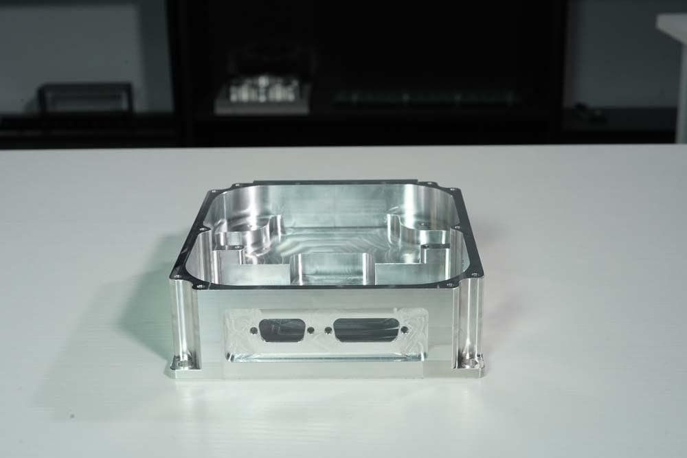
Face Milling vs. Peripheral Milling for Housings
Consider a custom aluminum gearbox housing.
The component may require:
- Mounting face
- Side walls
- Bearing bores
- Pockets
- Bolt holes
Face milling is well suited to establishing the mounting surfaces.
Peripheral milling is used for:
- Outer geometry
- Pocket walls
- Internal shoulders
- Side faces
Boring may then finish the bearing seats.
The best manufacturing process is therefore determined feature by feature.
No single milling method produces the entire part optimally.
A Practical Example: Datum Face and Precision Wall
Consider a robotics mounting plate.
The drawing specifies:
Bottom surface: flatness controlled
Side rail: perpendicular to bottom surface
Locating holes: position relative to both
A logical sequence could be:
Step 1: Face Mill the Bottom
This establishes datum A.
Step 2: Refixture From Datum A
The part is located from the finished reference surface.
Step 3: Peripheral Mill the Side Rail
The wall is now generated relative to datum A.
Step 4: Machine the Locating Holes
Hole position can be controlled from the same datum structure.
This demonstrates why process sequence matters.
The choice between face milling and peripheral milling is not isolated from GD&T.
Face Milling vs. Peripheral Milling for Surface Finish
If the only specification is:
Ra ≤ 1.6 μm
either method may be capable of producing an acceptable surface under appropriate conditions.
But that does not mean they are interchangeable.
If the feature is a broad mounting surface, face milling is usually more efficient.
If the feature is a vertical locating wall, peripheral milling is the natural process.
The functional geometry should select the machining method first.
Surface finish should then be optimized within that process.
Roughing vs. Finishing
Both face milling and peripheral milling can be used for roughing and finishing.
The process parameters should change accordingly.
Roughing Priorities
- High material-removal rate
- Stable tool load
- Good chip evacuation
- Efficient cycle time
Finishing Priorities
- Dimensional accuracy
- Surface finish
- Geometric accuracy
- Low tool deflection
- Consistent cutting load
Trying to use one aggressive roughing pass as the final precision pass can compromise dimensional control.
For critical surfaces, leaving a predictable amount of finishing stock is usually more reliable.
Climb Milling vs. Conventional Milling
Climb and conventional milling are different concepts from face vs. peripheral milling.
Both face milling and peripheral milling can involve climb or conventional cutting depending on:
- Cutter rotation
- Feed direction
- Engagement
Climb Milling
Chip thickness starts relatively high and decreases toward zero.
Modern CNC machines generally favor climb milling for many applications because machine backlash is controlled and cutting behavior can be favorable.
Conventional Milling
Chip thickness starts near zero and increases through the cut.
It may still be useful in certain:
- Surface conditions
- Machine setups
- Interrupted operations
Do not confuse:
Face vs. peripheral milling
with:
Climb vs. conventional milling
They describe different aspects of the cutting process.
Which Method Is Faster?
There is no universal answer.
For a large flat surface, a face mill will normally be much more productive than covering the same area with a small end mill.
For a narrow wall or local profile, an end mill performing peripheral milling may be much more efficient because no large face-milling tool can access the feature.
Total manufacturing time also includes:
- Setup
- Tool changes
- Probing
- Toolpath length
- Finishing
- Inspection
This matters particularly for prototypes and small batches.
A specialized tool may reduce one machining operation by 30 seconds but require additional setup and tool management.
In a high-volume production run, that cycle-time reduction may be valuable.
For five custom parts, process flexibility may matter more.
Which Method Gives Better Dimensional Accuracy?
Neither process is inherently “more accurate.”
The controlled feature is different.
Face milling is naturally suited to controlling:
- Planar reference faces
- Thickness
- Broad mating surfaces
Peripheral milling is naturally suited to controlling:
- External size
- Side walls
- Profiles
- Shoulders
Actual accuracy depends on:
- Machine condition
- Workholding
- Tool rigidity
- Cutting parameters
- Material behavior
- Process sequence
- Inspection
Which Method Produces Better Flatness?
If the question refers to a broad top surface on a vertical machining center, face milling is usually the logical method.
But final flatness depends on much more than cutter type.
A precision-ground surface may still outperform milling when exceptionally tight flatness is required.
The manufacturing route might therefore become:
CNC face milling → stress relief if required → surface grinding
rather than attempting to force the milling process beyond what the component function requires.
When Should You Use Face Milling?
Face milling is generally the preferred choice when the objective is to:
- Establish a broad datum surface
- Reduce the thickness of a block or plate
- Machine a mounting surface
- Prepare raw stock
- Create a large flat face efficiently
- Remove surface scale or excess stock
- Produce a planar sealing or mating surface within milling capability
It is especially attractive when the cutter has clear access across the workpiece.
When Should You Use Peripheral Milling?
Peripheral milling is generally preferred when machining:
- Side walls
- External profiles
- Pocket walls
- Shoulders
- Steps
- Narrow edges
- Slots
- Contoured boundaries
It is also the logical choice when the cutter must access localized features that a large face mill cannot reach.
When Should You Use Both?
In most custom CNC parts.
For example, a machined aluminum enclosure may require:
Face milling
to establish the top and bottom mounting faces.
Peripheral milling
to machine the outer profile and internal walls.
Drilling and tapping
for fastener holes.
Boring
for precision bearing features.
One part can contain several different machining processes because each feature has a different function.
Design Considerations for Face and Peripheral Milling
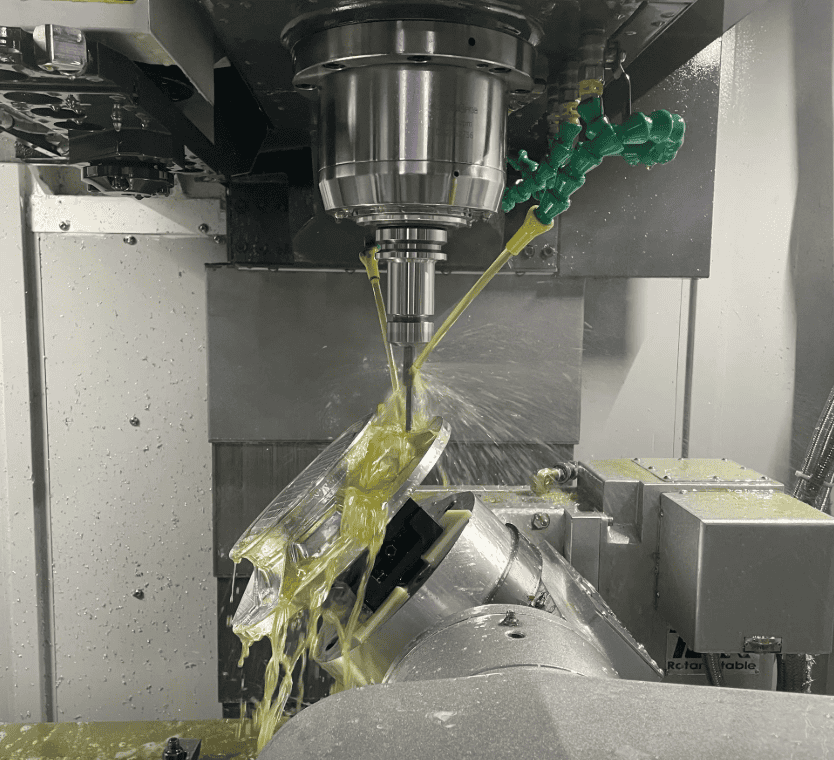
Engineers can reduce machining time and manufacturing risk by considering how the cutter will access the part.
Provide Face-Mill Clearance
Large face mills require room beyond the surface boundary.
Nearby raised features or clamps can prevent ideal cutter motion.
Avoid Unnecessarily Tall Thin Walls
Peripheral milling becomes more difficult as tool reach and wall flexibility increase.
Use Practical Internal Radii
Very small internal corner radii require smaller tools and reduce cutter rigidity.
Distinguish Functional Faces
Do not apply tight flatness or roughness specifications to every machined surface.
Define Datum Relationships
If a side wall must be perpendicular to a base face, communicate that relationship directly.
Consider the Manufacturing Sequence
A tolerance that appears easy in isolation may become more difficult after the part is flipped or re-fixtured.
How to Specify Milled Surfaces on an Engineering Drawing
Avoid simply writing:
FACE MILL
or:
MILL SURFACE
unless the manufacturing method itself is essential.
The drawing should primarily define the required result.
Depending on function, this may include:
- Dimensional tolerance
- Flatness
- Parallelism
- Perpendicularity
- Profile
- Position
- Surface roughness
For example, a mounting surface may need:
Flatness 0.05 mm
while a locating wall may require:
Perpendicularity 0.03 mm to datum A
These requirements communicate much more useful information than naming the preferred cutter.
Should You Specify Surface Roughness on Every Milled Surface?
Usually not.
Every additional requirement creates:
- Process constraints
- Inspection work
- Potential scrap risk
If a nonfunctional clearance surface only needs to avoid interference, there may be little value in specifying an unusually fine finish.
Surface requirements should correspond to function.
Critical areas may include:
- Bearing seats
- Seal surfaces
- Precision locating faces
- Sliding interfaces
- Optical mounting surfaces
Other surfaces may simply require standard machined finish.
Inspection of Face-Milled Surfaces
Depending on the drawing, inspection may include:
- Height measurement
- Surface plate and indicator
- CMM
- Surface roughness measurement
- Flatness evaluation
The correct method depends on whether the drawing controls:
- Height
- Flatness
- Parallelism
- Roughness
A profilometer reading alone cannot establish overall flatness.
Inspection of Peripheral-Milled Surfaces
Inspection may include:
- Micrometers
- Calipers
- Height gauges
- CMM
- Indicators
- Surface roughness measurement
For tall precision walls, inspection may need to check multiple heights to detect:
- Taper
- Bow
- Local deflection
A single measurement near the top of a wall may not represent the entire feature.
Common Face Milling Problems
Uneven Cutter Marks
Potential causes include:
- Insert height variation
- Spindle runout
- Toolholder runout
- Worn inserts
Poor Flatness
Potential causes include:
- Workpiece distortion
- Fixture deformation
- Machine geometry
- Residual stress
Chatter
Potential causes include:
- Weak workholding
- Excessive engagement
- Poor cutter selection
- Machine instability
Poor Surface Finish
Potential causes include:
- Incorrect feed
- Tool wear
- Built-up edge
- Insert runout
Common Peripheral Milling Problems
Wall Taper
Often related to:
- Tool deflection
- Excessive tool length
- High radial cutting forces
Chatter
May result from:
- Long tool overhang
- Poor workholding
- Unstable engagement
Dimensional Error
Possible causes include:
- Cutter deflection
- Tool wear
- Thermal effects
- Incorrect compensation
Mismatch Lines
These may appear when a tall wall is machined in multiple axial levels.
Finishing strategy and cutter reach should be planned to minimize them.
Face Milling and Peripheral Milling in Prototype Machining
Prototype parts often favor flexibility.
A machining center may use a limited set of versatile tools to produce a one-off or very small batch.
For example, an end mill may be used to perform:
- Pocket roughing
- Peripheral profiling
- Small-area facing
even though a dedicated face mill could machine one particular surface faster.
This may make sense when:
- Quantity is low
- Setup time matters more than cycle time
- The design is likely to change
- Tooling flexibility is valuable
The fastest individual cutting operation is not always the fastest way to deliver the prototype.
Face Milling and Peripheral Milling in Small-Batch Production
Once a prototype design becomes stable and moves into repeated small batches, the machining strategy can be optimized.
Suppose an aluminum housing progresses through:
5 prototypes → 30 parts → 100 parts
During prototype manufacturing, flexible tooling may be sufficient.
For repeat production, it may become worthwhile to optimize:
- Face-mill diameter
- Insert grade
- End-mill geometry
- Tool engagement
- Fixturing
- Probing
- Tool offsets
- Finishing strategy
The geometry of the part does not change.
The manufacturing process becomes more repeatable and economical.
This is particularly important in small-batch custom precision machining, where production quantities are large enough for process optimization to matter but often too small to justify dedicated mass-production tooling.
How 6CNC Approaches Milling Process Selection
For custom CNC parts, the decision is rarely “face milling or peripheral milling” for the entire component.
The more useful approach is to evaluate each functional feature.
A typical precision part may use:
Face milling for reference and mounting surfaces.
Peripheral milling for walls, shoulders, and profiles.
5-axis machining for difficult access or multi-face geometry.
Boring for critical internal diameters.
Grinding when final flatness or surface requirements exceed milling capability.
At 6CNC, prototype and small-batch parts are planned around the complete drawing, material, feature access, tolerances, inspection requirements, and expected production quantity rather than forcing every feature into a single machining strategy.
Face Milling vs. Peripheral Milling: How to Choose
Use the following questions.
What surface are you machining?
Broad top face → consider face milling.
Side wall or profile → consider peripheral milling.
Is the surface a primary datum?
A dedicated face-milling strategy may provide a more efficient way to establish a broad reference surface.
Does the feature require a square shoulder?
Tool geometry becomes important. A 90° shoulder cutter or end mill may be necessary.
Is the wall tall or flexible?
Peripheral tool deflection must be evaluated.
Is the surface very wide?
A larger face mill may substantially reduce machining time.
Is access restricted?
An end mill may reach features that a face mill cannot.
Is production quantity low?
A versatile cutter may sometimes be more economical than adding dedicated tooling.
Is the required flatness beyond milling capability?
Consider a secondary process such as surface grinding rather than over-constraining the milling operation.
Final Comparison
Face milling and peripheral milling are not competing technologies where one process should replace the other.
They solve different geometric problems.
Face milling is primarily suited to broad planar surfaces perpendicular to the cutter axis. It is efficient for establishing datum faces, machining mounting surfaces, preparing stock, and controlling large flat areas.
Peripheral milling uses the cutter circumference to generate surfaces parallel to the tool axis. It is essential for machining profiles, walls, shoulders, edges, and many pocket features.
The most important differences are not only cutting direction.
They also affect:
- Tool selection
- Cutting-force direction
- Tool deflection
- Surface texture
- Cutter access
- Material-removal strategy
- Workholding
- Inspection
- Process sequence
For many precision CNC parts, the optimal process uses both.
A face-milled surface may establish the reference datum. Peripheral milling then creates walls and profiles relative to that datum. Other processes such as drilling, boring, 5-axis milling, grinding, or honing may then complete the remaining functional features.
The goal is not to choose the process with the best theoretical specification.
It is to select the machining sequence that produces the required part accurately, repeatably, and economically.
For prototype and small-batch custom parts, send 6CNC the complete CAD model and engineering drawing so that critical faces, walls, datums, tolerances, tool access, and inspection requirements can be reviewed together before production.
Frequently Asked Questions
What is the main difference between face milling and peripheral milling?
Face milling primarily generates a surface perpendicular to the cutter axis, while peripheral milling mainly uses the cutter circumference to generate surfaces parallel to the cutter axis.
What is face milling used for?
Face milling is commonly used for broad flat surfaces, datum faces, mounting surfaces, stock preparation, and controlling plate or block thickness.
What is peripheral milling used for?
Peripheral milling is commonly used for side walls, external profiles, shoulders, steps, pocket walls, slots, and other surfaces generated with the side of the cutter.
Is peripheral milling the same as end milling?
Not exactly. Peripheral milling describes the cutting action, while an end mill is a type of tool. End mills are commonly used for peripheral milling but can perform several other operations.
Is face milling the same as end milling?
No. Face milling is an operation primarily intended to generate a planar surface perpendicular to the tool axis. An end mill can perform limited facing operations, but a dedicated face mill is generally more efficient for large surfaces.
Can an end mill perform face milling?
Yes. The bottom cutting edges of an end mill can machine flat surfaces perpendicular to the tool axis. This is common inside pockets and on small areas. For large surfaces, a dedicated face mill is usually more productive.
Can peripheral milling create a flat surface?
Yes. Peripheral milling can create precision flat side walls, and traditional slab milling uses peripheral edges to create broad flat surfaces parallel to the cutter axis.
Which gives a better surface finish: face milling or peripheral milling?
Either can produce an excellent finish. The result depends on tool geometry, runout, rigidity, feed, cutting speed, tool wear, engagement, and the geometry of the machined feature.
Which milling method is more accurate?
Neither is universally more accurate. Face milling is naturally suited to broad planar surfaces, while peripheral milling is suited to walls and profiles. Accuracy depends on the complete machining setup.
Which process is faster?
For a wide flat surface, a face mill is usually more efficient. For local walls, profiles, shoulders, or narrow features, peripheral milling is generally more appropriate. Total cycle time also depends on setup and tool changes.
Why does peripheral milling cause wall taper?
Radial cutting forces can deflect the end mill or workpiece. Long tool overhang, small cutter diameter, high engagement, and thin walls increase the risk.
Why do face-milled surfaces sometimes show cutter marks?
Possible causes include insert runout, differences in insert height, cutter path, feed rate, spindle condition, or material buildup on the cutting edge.
Is surface roughness the same as flatness?
No. Roughness describes small-scale surface texture. Flatness describes how closely the overall surface follows a plane. A smooth surface can still have poor flatness.
Should a drawing specify face milling or peripheral milling?
Usually the drawing should define the functional requirement—such as flatness, perpendicularity, profile, dimension, or surface finish—and allow the manufacturer to select the most appropriate process unless the manufacturing method itself is mandatory.
What cutter is used for face milling?
Common tools include indexable face mills, shell mills, 45-degree face mills, 90-degree shoulder cutters, and high-feed cutters depending on the application.
What cutter is used for peripheral milling?
Solid-carbide end mills, indexable end mills, side milling cutters, shell mills, and slab mills can all perform peripheral cutting depending on the machine and feature.
Is face milling suitable for aluminum?
Yes. Aluminum can be face milled at high productivity using sharp, aluminum-specific cutting geometry and appropriate chip evacuation.
Can both face milling and peripheral milling be used on the same part?
Yes. This is extremely common. Face milling may establish reference surfaces while peripheral milling produces walls, shoulders, and profiles relative to those datums.
Which process is better for prototype and small-batch CNC parts?
The correct process depends on individual part features rather than production quantity alone. Low-volume work may favor versatile tooling, while repeated small batches may justify optimized face mills, end mills, fixtures, and finishing strategies.