Energy equipment places unusual demands on machined components. A wind-turbine shaft, hydrogen manifold, hydroelectric bearing housing, geothermal valve, and battery cooling plate may all belong to the same broad industry, but the conditions they face—and therefore the way they must be manufactured—can be completely different. For examples of how materials, sealing interfaces and inspection shape the process, read our guide to CNC machining for renewable energy.
Some components operate under high pressure or corrosive fluids. Others need to maintain shaft alignment over long distances, survive continuous cyclic loading, or provide sealing surfaces that remain reliable after years of service. In many energy applications, dimensional accuracy is only one part of the requirement. Material condition, surface finish, runout, internal cleanliness, corrosion resistance, documentation, and traceability can be equally important.
CNC machining is especially valuable in this environment because it can be used both as a primary manufacturing process and as a precision finishing process after casting, forging, fabrication, or additive manufacturing. It is also well suited to prototypes, engineering validation, replacement parts, and small production runs where dedicated high-volume tooling would be difficult to justify.
The important question is therefore not simply whether an energy component can be CNC machined. It is how the machining process should be planned around the way that component actually functions.
Why CNC Machining Matters in Energy Equipment
Energy-sector parts often stay in service far longer than ordinary consumer components. A failed bearing housing in a wind turbine, leaking valve in a hydrogen system, or worn shaft in a hydroelectric installation can create downtime that costs far more than the part itself. This is why machining strategy in the energy sector is usually driven by functional interfaces rather than by general dimensional accuracy alone.
A cast pump housing, for example, may already have its overall shape, but the bearing bores, mounting faces, seal interfaces, and threaded ports still need controlled machining. A forged shaft may already have the required mechanical properties, but its journals, keyways, shoulders, and flange faces need to be finished relative to one consistent rotational axis. In other cases, machining from billet may be the most economical route because only a few parts are needed and the design may still change.
That combination of precision and flexibility explains why CNC machining appears throughout wind, oil and gas, hydrogen, hydroelectric, geothermal, conventional power generation, solar tracking, and energy-storage equipment.
CNC Machining for Wind Energy
Wind-turbine components are often difficult because of their physical scale, long service life, and rotating function. Main shafts, gearbox housings, bearing housings, hubs, pitch-system parts, yaw components, couplings, and hydraulic hardware all rely on machined interfaces even when the original blank begins as a forging or casting.
A large gearbox housing illustrates why size alone can become a manufacturing challenge. The geometry may not be especially complicated, but several bearing bores may need to remain correctly positioned and aligned across a heavy casting. Machine travel, lifting capacity, fixture rigidity, thermal stability, and inspection access all become part of the process. The challenge is not merely holding the diameter of one bore; it is preserving the relationship between several bores after large amounts of material have been removed.
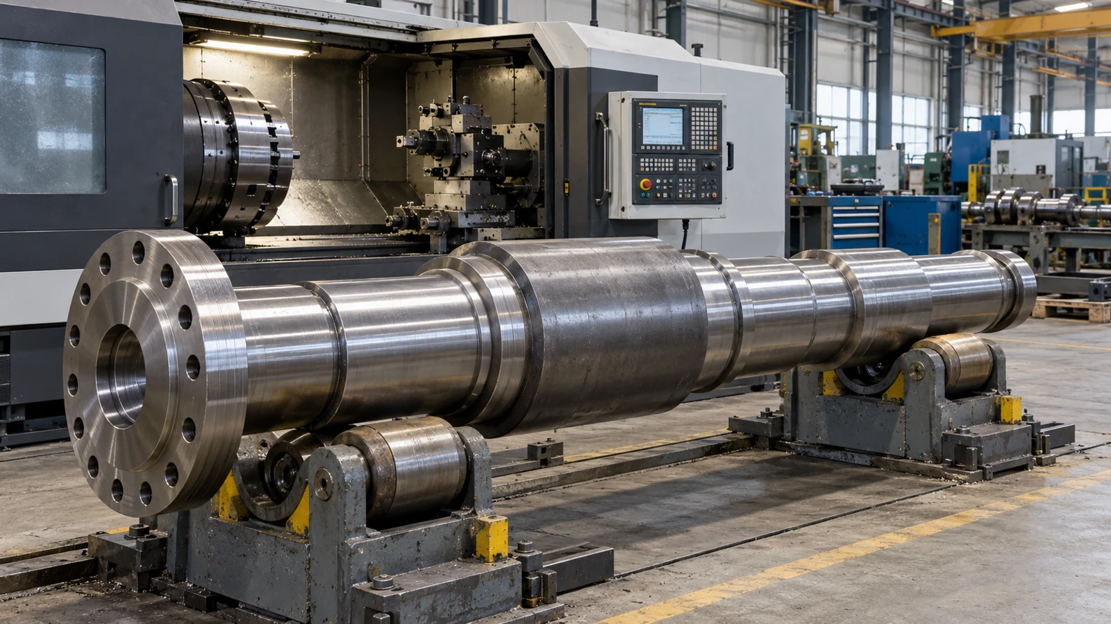
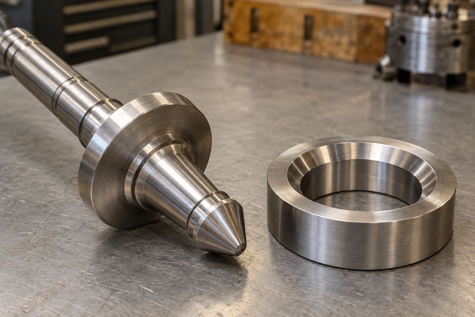
Main shafts create a different problem. A typical shaft may pass through rough turning, heat treatment, finish turning, milling of keyways or flange features, and finally cylindrical grinding on critical bearing journals. The sequence matters because heat treatment can move the part, and finish turning is usually used to restore geometry before the most critical journals are ground to final size. The final inspection then focuses on diameter, runout, coaxiality, and surface finish relative to the established shaft datum.
This is a good example of why a visually simple part can be harder to manufacture than a complex five-axis component. The geometry may consist mostly of cylinders and shoulders, but controlling a long rotational axis over several machining stages demands careful support, datum control, and inspection.
Wind maintenance also creates demand for repair and replacement parts. Turbines can remain in service for many years, and certain components may no longer be available from the original supplier. In those cases, CNC machining becomes useful not only for new production but also for reproducing obsolete shafts, bushings, housings, and repair hardware in very low quantities.
CNC Machining for Oil and Gas Equipment
Oil and gas components are usually driven by pressure, corrosion, sealing, thread integrity, and internal flow geometry. Valve bodies, manifolds, pressure housings, flanges, stems, connectors, pump parts, compressor parts, and drilling-system components may operate in environments where a small defect has much greater consequences than a cosmetic machining mark.
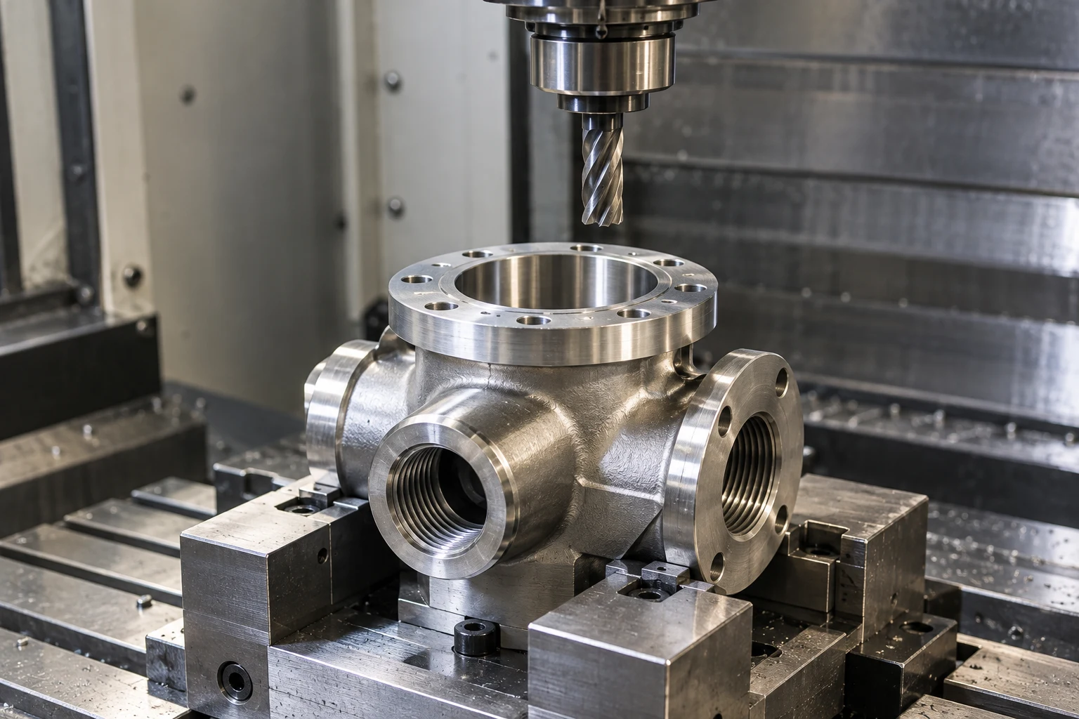
A valve body is a good example. At first glance, it may resemble a conventional machined block. Internally, however, it can contain intersecting passages, threaded ports, seats, bores, and flange interfaces. The outside dimensions may be relatively ordinary while the true functional requirements are concentrated around seat concentricity, bore location, thread form, and sealing geometry.
A practical process might rough machine the outside shape and major internal passages first, leaving the valve seat and flange interfaces with finishing allowance. Ports are then drilled and threaded, internal intersections are deburred, and only after most material removal is complete are the sealing seat and flange faces finished under lighter cutting conditions. This keeps the highest-value functional surfaces away from the heaviest cutting operations.
Why sealing surfaces need more than a low Ra value
Sealing is one area where drawings are often oversimplified.
An O-ring groove, flat gasket, metal-to-metal seat, and mechanical seal do not all need the same type of surface. An O-ring groove depends heavily on groove geometry, compression, edge condition, and a surface that does not provide a leakage path across the seal. A gasketed flange places more emphasis on overall flatness and contact pattern. A metal seal may require much tighter control of local geometry because there is less compliant material available to absorb error.
Mechanical seal faces can be more demanding still. Depending on the design, conventional milling or turning may only create the preliminary geometry, with grinding or lapping used afterward to establish the required flatness and finish.
This is why simply specifying “Ra 0.8” everywhere is not a substitute for understanding the sealing system. Waviness, flatness, tool-mark direction, and isolated surface defects can matter just as much as the arithmetic roughness value.
Internal passage quality
Manifolds and valve bodies also create an inspection problem that is easy to overlook: the dangerous defect may be inside the part.
When two drilled holes intersect, a burr can remain at the intersection even though every external feature looks correct. That burr may later detach, restrict flow, contaminate a downstream valve, or damage a seal. Internal deburring therefore needs to be designed into the process rather than left until the final visual inspection.
CNC Machining for Hydrogen and Fuel-Cell Systems
Hydrogen hardware introduces many of the same pressure and sealing issues found in other fluid systems, but material compatibility and cleanliness become particularly important.
Typical machined parts include manifolds, regulators, valve bodies, compressor components, sensor housings, test fixtures, and fuel-cell support hardware. A manifold may contain several pressure ports, sensor connections, valve interfaces, and internal passages packed into one relatively compact component.
The difficulty is not drilling each hole individually. It is maintaining their positional relationships, controlling thread quality, removing burrs from internal intersections, protecting sealing surfaces, and keeping the internal system clean.
This is also an application where low-volume CNC machining is particularly useful during development. A hydrogen test program may begin with twenty stainless steel manifolds. After testing, engineers may decide to move one sensor port or change a valve interface. With CNC machining, the next batch can use the revised CAD model without creating new casting or molding tooling.
That flexibility matters because early-stage energy systems often evolve in small increments rather than moving immediately into high-volume production.
For hydrogen–material interactions and compatibility research, see the DOE H-Mat consortium.
CNC Machining for Hydroelectric Equipment
Hydroelectric systems combine large component size with long service life, water exposure, and a strong need for maintenance capability.
Typical machined components include turbine shafts, bushings, bearing parts, guide-vane components, valve hardware, housings, and gate-system parts. Many of these components may remain in service for decades, which means repair and refurbishment are almost as important as manufacturing new parts.
Large shafts require careful turning and support because their own weight and cutting forces can introduce deflection. Bearing and sealing regions may later be ground to restore final geometry. Large housings may require line boring or controlled machining of bearing seats that must remain aligned across considerable distances.
Hydroelectric maintenance also highlights the value of on-site or in-situ machining. Some components are too large, heavy, or expensive to remove easily from the installation. Portable machining equipment can be used for flange facing, journal restoration, line boring, or large-hole repair while the major equipment remains on site.
Factory machining is still preferred when the component can be removed and inspected under controlled conditions, but on-site machining is a distinctive part of energy maintenance because transportation and disassembly can sometimes cost more than the repair itself.
CNC Machining for Conventional Power Generation
Power-generation equipment frequently combines heat, rotation, wear, and long operating periods. Shafts, pump components, turbine-related parts, couplings, bearing housings, and valve hardware may therefore pass through several manufacturing processes before they are complete.
A rotating shaft might begin with turning, followed by heat treatment where required, then finish turning and grinding. A valve component may combine turned diameters, radial ports, threaded features, and milled flats, making mill-turn machining a more efficient option than moving the part between separate lathes and milling machines.
The critical point is that energy manufacturing is often a process chain, not a single-machine operation.
Turning removes the bulk geometry. Milling adds off-axis features. Grinding establishes final journal or sealing surfaces. Wire EDM may be used for narrow hardened features. The best process is the one that assigns each feature to the manufacturing method most suited to it.
CNC Machining for Nuclear Support Equipment
Nuclear-related projects add another dimension: documentation.
Not every machined part used around nuclear equipment is safety-critical, but projects can require strict material traceability, revision control, inspection records, and process documentation. A part may be dimensionally correct and still be unusable if the required certificate or traceability record is missing.
This changes how the job should be handled from the quotation stage. If material certificates, First Article Inspection, special inspection records, or controlled process documentation are required, those requirements need to be identified before production begins rather than requested afterward.
In these applications, quality paperwork is not administrative overhead added to a finished component. It is part of the deliverable.
CNC Machining for Solar Energy Equipment
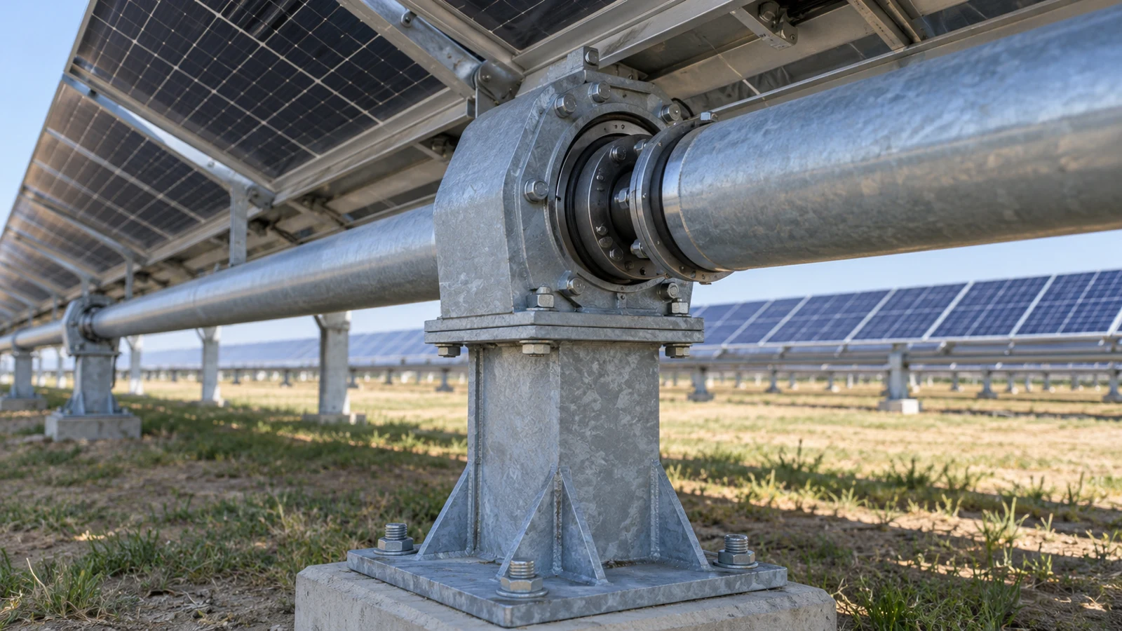
Solar manufacturing uses much less precision machining inside the photovoltaic panel itself than in the mechanical systems surrounding it. Tracking systems, actuator assemblies, drive components, motor mounts, bearing housings, sensor brackets, and production fixtures are more natural CNC applications.
A solar tracker bearing housing, for example, may need an accurate bore for the rotating shaft while the external structure only requires general machining tolerances. The part may also operate outdoors for years, so surface protection becomes part of the manufacturing plan.
A steel component may require plating or coating, while an aluminum housing may be anodized. If the coating affects a bearing fit or locating surface, the drawing should make clear whether the final dimension applies before or after finishing.
Solar tracking systems also show why not every dimension deserves the same tolerance. The bearing bore may directly affect motion and wear, while several external dimensions merely provide assembly clearance. Applying the same tight tolerance to the entire part increases machining and inspection cost without improving performance.
CNC Machining for Energy Storage
Energy storage increasingly uses CNC machining during battery development, thermal testing, and specialized low-volume production.
Typical components include cooling plates, module housings, thermal spreaders, structural plates, busbar fixtures, and test hardware.
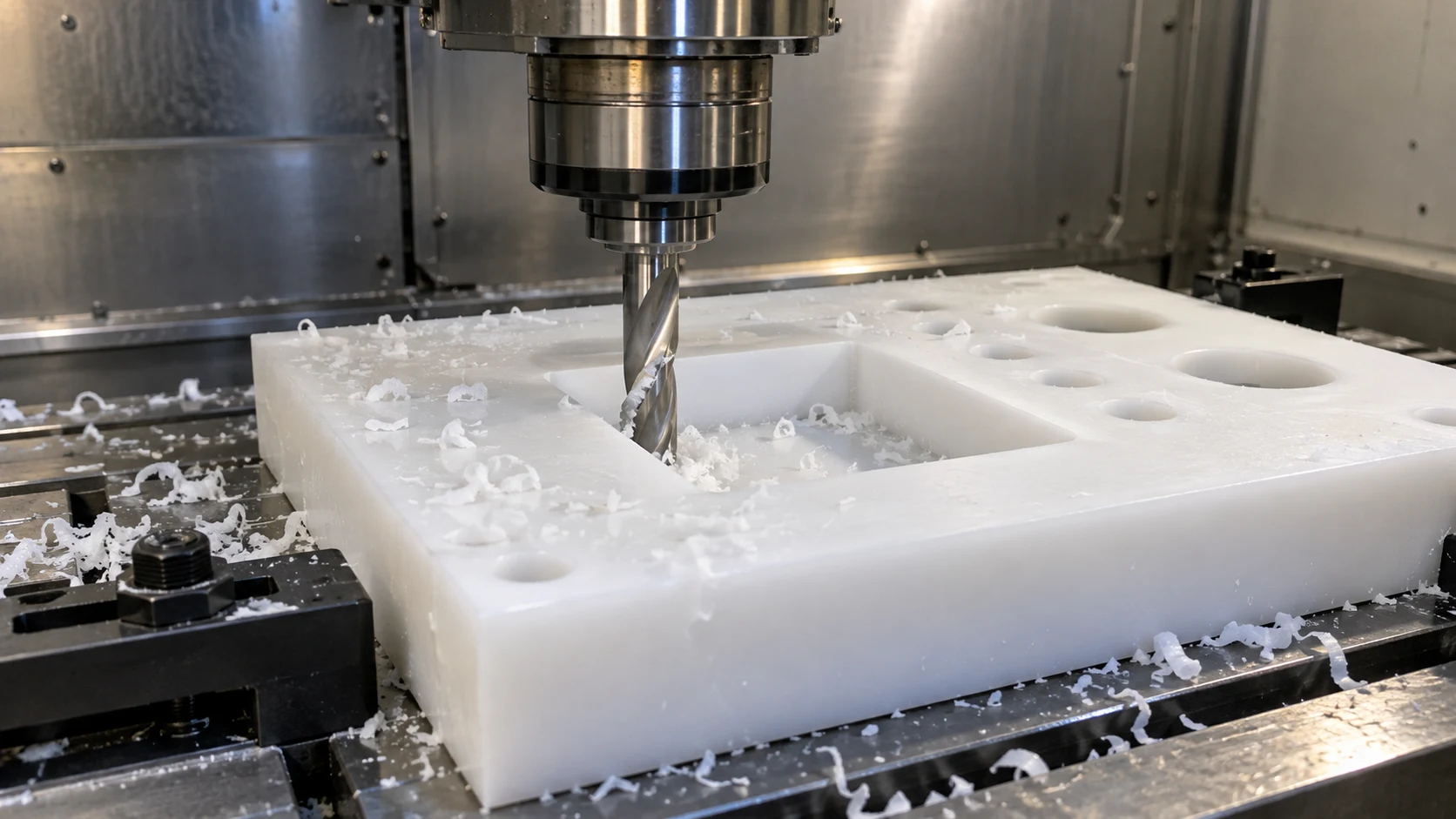
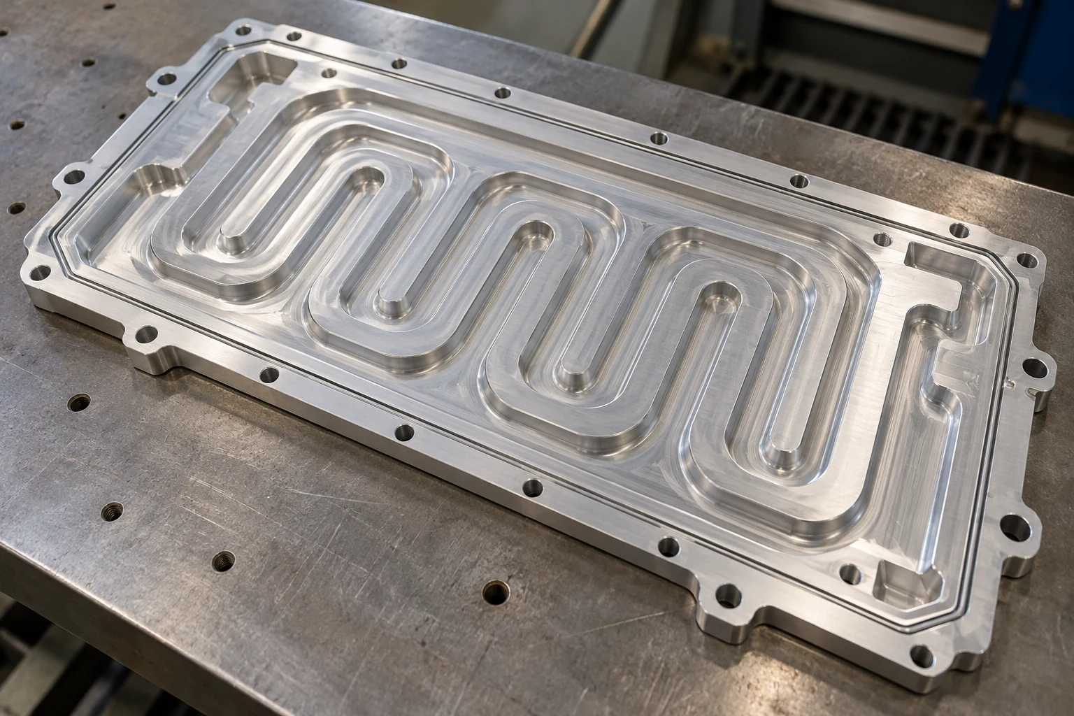
An aluminum battery cooling plate illustrates the interaction between geometry and function. The part may contain coolant passages, an O-ring groove, ports, and mounting holes. Most of the geometry can be roughed first, while the sealing surface is left for a later finishing pass after the part has released most of the stress associated with heavy material removal.
Flatness and groove geometry are then inspected before assembly. If the internal fluid path becomes too complex to machine directly, a different manufacturing route—such as brazed construction, bonded plates, or additive manufacturing—may be more appropriate.
The point is not to force every cooling design into CNC machining. It is to use CNC where it provides the best combination of precision, flexibility, and cost.
CNC Machining for Geothermal Equipment
Geothermal systems operate with heat, pressure, mineral-rich fluids, and potentially aggressive corrosion conditions. Pumps, valve components, flanges, drilling-system parts, sealing hardware, and sensor housings may therefore use stainless steels, nickel alloys, or other materials chosen primarily for service performance.
That creates an important tradeoff.
The materials that survive geothermal service best are often not the materials a machine shop would choose for productivity.
316 stainless steel machines more slowly than aluminum. Titanium provides strong corrosion resistance but concentrates heat at the cutting edge. Nickel-based alloys may tolerate severe environments but generate high cutting forces, work hardening, and rapid tool wear.
A professional machining strategy therefore starts with the required engineering material and develops the process around it. The supplier should not push the design toward an easier alloy simply to shorten cycle time unless the engineering team confirms that substitution is acceptable.
Common CNC-Machined Energy Components
Many component families appear repeatedly across different energy sectors, but the reason they are difficult varies by application.
| Component | Typical Energy Applications | Typical Processes | Main Manufacturing Challenge |
|---|---|---|---|
| Shafts | Wind, hydro, power generation | Turning, milling, grinding | Runout, coaxiality and journal finish |
| Valve bodies | Oil & gas, hydrogen, geothermal | Milling, drilling, boring | Pressure interfaces and sealing |
| Manifolds | Hydrogen, oil & gas, test systems | Milling, deep drilling | Port accuracy, internal burrs and cleanliness |
| Bearing housings | Wind, hydro, turbines | Milling, boring | Bore position and alignment |
| Flanges | Oil & gas, hydro, geothermal | Turning, milling | Flatness and sealing-face quality |
| Pump components | Hydro, geothermal, oil & gas | Milling, turning | Wear, corrosion and fits |
| Impellers | Pumps, compressors, power systems | 5-axis milling | Blade geometry and cutter access |
| Couplings | Wind, hydro, power generation | Turning, milling | Concentricity and fit |
| Cooling plates | Battery and energy storage | Milling, drilling | Flatness, sealing and channels |
| Repair parts | Hydro, wind, legacy power systems | Turning, milling, grinding | Restoring original function from worn components |
Materials for Energy CNC Machining
Material selection should reflect the actual service environment rather than machining convenience.
Carbon and alloy steels such as 1045, 4140, and 4340 are common in shafts, couplings, heavy structural parts, and other applications where stiffness, strength, and wear resistance matter. Heat treatment can significantly improve mechanical properties, but it can also affect final machining strategy because critical surfaces may need to be restored or ground afterward.
Stainless steels such as 304, 316, and 17-4PH are common in valves, pump components, manifolds, and fluid-handling systems. 316 is particularly useful where corrosion resistance matters, while 17-4PH can provide higher strength. Their improved service performance comes with higher cutting forces and more demanding heat and tool-wear control than aluminum.
Aluminum alloys such as 6061 and 7075 appear more often in control systems, energy-storage equipment, electronics housings, lightweight structures, and test hardware. They are relatively efficient to machine, but they are not substitutes for steel or stainless steel where pressure, wear, or temperature requirements dominate.
Titanium and nickel-based alloys are used more selectively. Their corrosion, temperature, or strength advantages can justify the additional material and machining cost in harsh environments. The manufacturing challenge is to manage that cost without compromising the properties that motivated the material selection in the first place.
Copper and copper alloys appear in electrical and thermal hardware. Their conductivity is valuable, but their ductility can produce burrs and chip-control problems that require sharp tooling and suitable machining parameters.
Large-Part Machining Changes the Process
As parts become larger, tolerance control becomes less about the nominal capability of the CNC machine and more about the complete manufacturing system.
A large steel housing changes dimension with temperature. A long shaft can sag under its own weight. A heavy casting can distort when clamped incorrectly. Large components also require planned lifting, rigging, and inspection.
The measurement system needs to match the size and tolerance of the part as well. There is little value in machining a large bearing seat to a demanding specification if the shop cannot verify its position relative to the surrounding datum structure.
This is why large energy components should be reviewed as a complete machining-and-inspection problem before production begins.
3-Axis, 5-Axis, Turning, Mill-Turn, Grinding and EDM
The correct machining process follows the geometry.
A shaft is naturally suited to turning. A manifold is mainly a milling and drilling problem. An impeller benefits from five-axis access. A rotational component with radial ports may be ideal for mill-turn. A hardened bearing journal may need grinding. A narrow profile in hardened conductive material may be better produced with Wire EDM.
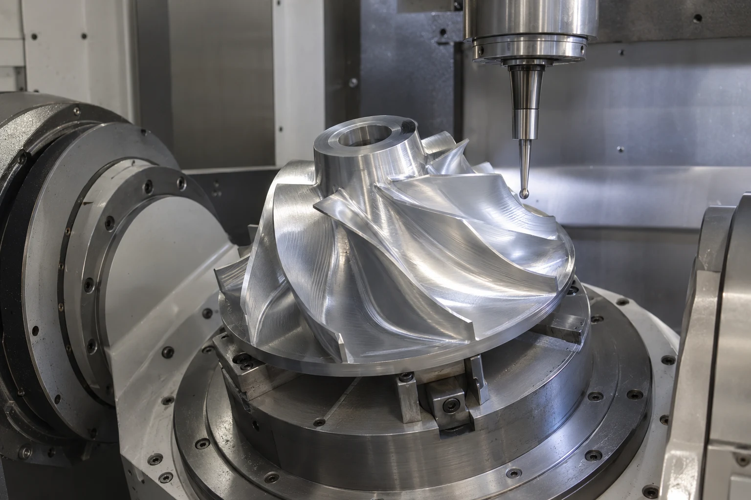
Five-axis machining is therefore not automatically “better” for energy components. It becomes useful when the tool needs improved access, the part contains several orientations, or complex surfaces such as impeller blades require changing tool direction.
In an impeller, for example, neighboring blades restrict cutter access while each blade twists around the hub. Simultaneous five-axis motion allows tool orientation to change as the cutter moves through the blade channel, helping reduce tool length and maintain a more useful cutting angle.
The same technology provides little value on a simple flange that can be turned efficiently in one setup.
Repair and Reverse Engineering: Restore Function, Not Wear
One of CNC machining’s most valuable roles in the energy industry is producing replacement components for equipment that may have been in service for decades.
Sometimes an original drawing exists. Sometimes it does not.
When a usable drawing is unavailable, reverse engineering may involve CMM measurement, micrometers, bore gauges, 3D scanning, material identification, and CAD reconstruction.
But a worn component should not simply be copied.
Imagine a bushing whose original bore was 50.00 mm but has worn to 50.35 mm after years of service. Reproducing the measured 50.35 mm dimension would recreate the failure condition rather than restore the original fit.
A proper reconstruction should therefore separate:
- original functional geometry;
- wear;
- deformation;
- repair modifications;
- intentionally designed clearances.
Unworn reference surfaces, mating components, assembly dimensions, historical drawings, and engineering knowledge all help reconstruct the original design intent.
That ability to restore function rather than worn geometry is one of the most important differences between simple copying and real reverse engineering.
Prototype to Small-Batch Production
Energy development rarely moves directly from one prototype to mass production.
A hydrogen project may need five initial valve bodies, twenty validation manifolds, and one hundred pilot-production units. A battery program may test several cooling-channel designs before choosing the final version. Specialized industrial energy systems may never exceed a few hundred units per year.
CNC machining fits this pattern well because the design can change between batches without replacing expensive hard tooling.
The process can also mature as the quantity increases. A first prototype may use simple workholding and extensive manual inspection. A fifty-piece batch may justify dedicated soft jaws, First Article Inspection, and planned checks of critical dimensions. A recurring production order may use controlled tool-life limits, probing, repeat fixtures, and documented inspection intervals.
The CAD model may stay the same while the manufacturing system becomes more production-oriented.
First Article Inspection and In-Process Control
Energy parts can contain expensive material and long machining cycles, so discovering an error only after the complete batch is finished is a costly way to control quality.
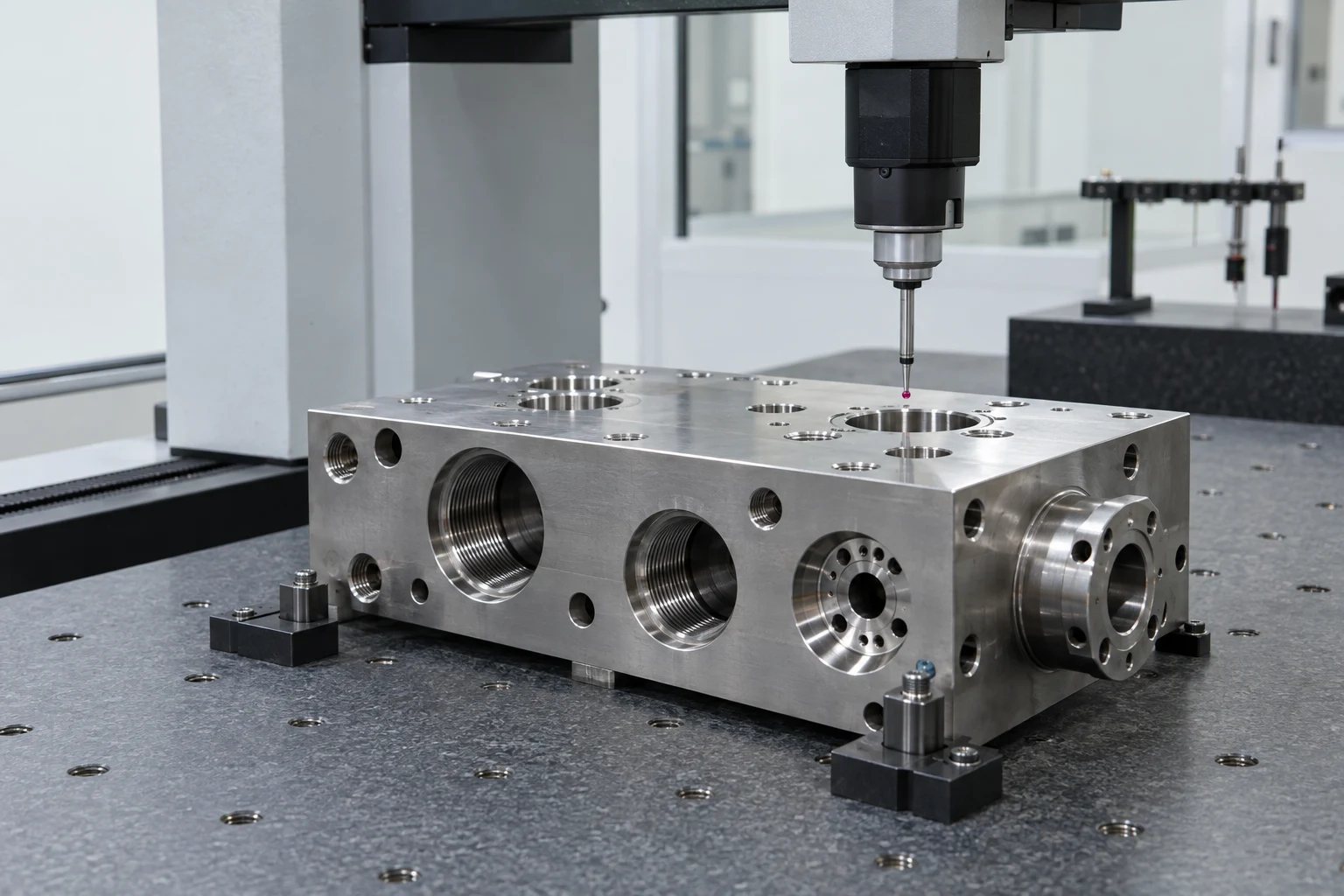
First Article Inspection provides an early checkpoint. The first completed part can confirm that the program, fixture, material, tooling, and inspection method are working together correctly before the remainder of the order is released.
In-process inspection then becomes useful for features that are sensitive to tool wear or process drift.
A bearing bore in a 100-piece housing order might be checked periodically during production. If measurements begin trending toward the tolerance limit, the tool or offset can be reviewed before nonconforming parts are produced.
Not every dimension needs this level of attention.
The inspection plan should prioritize the features that actually control:
- sealing;
- alignment;
- bearing fits;
- pressure interfaces;
- rotation;
- assembly.
Traceability and Documentation
In some energy projects, the manufacturing record is almost as important as the part.
Requirements may include material certificates, heat numbers, lot traceability, First Article reports, dimensional reports, certificates of conformance, coating records, and revision-controlled process documentation.
These requirements should be defined in the RFQ.
If a customer requests full material traceability only after production has already started, the supplier may no longer be able to reconstruct the necessary documentation reliably.
The safest approach is to treat documentation requirements the same way as dimensional requirements: define them before the manufacturing route is finalized.
DFM Guidelines for Energy Components
Good DFM for energy parts is not about simplifying every component. Many difficult features exist for valid functional reasons. The goal is to distinguish necessary complexity from complexity that adds cost without improving performance.
The first step is identifying function-critical dimensions. Bearing fits, seal interfaces, pressure bores, shaft journals, and alignment features may deserve close tolerances, while several outer dimensions may only need to satisfy assembly clearance. This distinction can significantly affect machining time, inspection effort, and quotation.
Deep narrow cavities and passages should also be reviewed carefully because they increase tool reach and chip-evacuation difficulty. Internal corner radii should be made as large as function allows so stronger cutters can be used. Coating thickness should be considered around precision fits, and drawings should clearly state whether the final dimension applies before or after plating or coating.
Material should be specified fully as well. “Stainless steel” is rarely enough for a demanding energy component. Grade, condition, heat treatment, and any required material certification should be stated explicitly.
Finally, inspection expectations should be defined early. If the project requires CMM reporting, FAI, roughness measurement, or lot traceability, those requirements belong in the manufacturing plan rather than being added after quotation.
Practical Manufacturing Examples
316 Stainless Steel Valve Body
Consider a 316 stainless valve body used in a corrosive fluid system. The part contains a main flow bore, threaded side ports, a sealing seat, mounting flange, and actuator interface.
The outside and major internal geometry are rough machined first. The seat and sealing flange are intentionally left with finishing allowance so that they are not exposed to the distortion and tool loading associated with the heaviest material removal. Ports are then drilled and threaded, and the intersecting passages are deburred while they are still accessible.
Only after the major geometry has stabilized are the seat and sealing face finished. Inspection focuses on the features that determine pressure performance: seat geometry, bore relationships, thread condition, flange quality, and sealing-surface finish. The part may then receive passivation according to the specified requirement.
This is a better manufacturing strategy than applying equal precision to every visible surface.
Long Alloy-Steel Shaft
A long wind or power-generation shaft may contain bearing journals, threaded ends, a flange, and a keyway.
The component is rough turned first to establish the main rotational geometry. If the material requires heat treatment, this is performed before final dimensional work because the thermal cycle can change the shaft slightly. Finish turning then brings the part close to final size, while keyways or flange features are machined relative to the established axis.
Critical bearing journals are ground last because grinding can provide the roundness, cylindricity, diameter control, and finish required at those interfaces. Final inspection evaluates the journals relative to the shaft datum rather than simply checking each diameter independently.
The part looks simple. The process is not.
Prototype Hydrogen Manifold
A hydrogen development program may require twenty stainless test manifolds containing pressure ports, sensor connections, valve interfaces, and mounting features.
The main machining challenge is controlling the relationship between those features while also ensuring the internal system is clean and free from burrs. Ports are drilled and threaded, sealing regions are protected during subsequent operations, and internal intersections are carefully deburred.
After testing, the engineering team may move one sensor port or revise a valve connection. The next batch can be produced directly from the updated CAD model without new casting tooling.
This is exactly the kind of development environment where low-volume CNC machining is more valuable than high-volume manufacturing efficiency.
Battery Cooling Plate
An aluminum battery cooling plate may include coolant passages, an O-ring groove, connection ports, and mounting holes.
The main geometry is machined first. Material removal is balanced so the plate does not distort unnecessarily, while the final sealing surface is left until later in the process.
After most internal material has been removed, the face is finished and the O-ring groove is machined to its final dimensions. Flatness and groove geometry are then checked before assembly.
If later thermal analysis produces a channel design that is inaccessible to conventional cutting tools, the manufacturing route may change to brazed construction, bonded plates, or additive manufacturing. The correct process should follow the cooling geometry rather than forcing the design to remain machinable from billet.
Solar Tracker Bearing Housing
A solar tracker may use an aluminum or steel housing to support a shaft and bearing assembly.
The bearing bore is function-critical because it controls shaft support and alignment. Several outer surfaces and mounting features may only require normal production tolerances.
The machining strategy therefore focuses the tightest process control on the bore and its relationship to the mounting datums. The external surfaces are machined more economically.
After machining, the housing may receive anodizing, plating, or another corrosion-resistant finish appropriate for outdoor exposure, with coating buildup accounted for around any precision fits.
Geothermal Valve Component
A geothermal valve component may need to survive hot, mineral-rich fluid.
The engineering team selects a corrosion-resistant stainless or nickel-based alloy. That decision immediately changes the machining strategy because the material produces more heat, higher cutting force, and faster tool wear than aluminum or mild steel.
Instead of replacing the alloy with an easier material, the process is adapted around the service requirement. Cutting engagement is controlled, tooling is selected for the alloy, and the finishing sequence is planned to protect sealing and pressure-critical surfaces.
The manufacturing cost is higher—but the material exists for a reason.
Choosing a CNC Supplier for Energy Components
A supplier should be selected according to the actual part risk rather than simply because its website lists “energy” as an industry.
A company producing excellent small aluminum housings may not be the right choice for a long alloy-steel shaft. A heavy-machining shop optimized for large castings may not be the best supplier for a compact precision hydrogen manifold.
Useful questions include whether the supplier can handle the required part size, whether it regularly machines the specified material, whether turning, 5-axis machining, grinding, or EDM are available where needed, and whether the inspection equipment matches the critical geometry.
For prototype and small-batch projects, it is also useful if the supplier can move with the development program. A project may begin with a handful of parts and later grow into recurring orders of dozens or hundreds. The machining, fixturing, and inspection strategy should be able to mature without forcing the customer to restart the complete supply chain.
For 6CNC projects, the same principle applies: the process is selected around the part. A valve body may require milling and boring, a shaft may combine turning and grinding, while an impeller or complex multi-face component may justify five-axis machining. CMM, optical measurement, roughness measurement, and material verification can then be applied according to the drawing and project requirements rather than as generic inspection steps.
Final Thoughts
Energy-sector CNC machining is difficult because different components fail in different ways.
A wind shaft depends on rotational alignment and journal condition. A hydrogen manifold depends on clean internal passages, threads, and sealing interfaces. A geothermal valve depends on both corrosion-resistant material and reliable sealing geometry. A battery cooling plate depends on flatness and coolant integrity.
The goal is therefore not simply “high precision.”
It is precision applied to the features that actually determine performance.
That means identifying which surfaces seal, which features rotate, which dimensions control alignment, which materials need traceability, and which processes are best suited to each functional requirement.
For prototypes and small-batch production, CNC machining provides a particularly useful balance between engineering flexibility and production-grade performance. Designs can change between batches, replacement parts can be produced without dedicated tooling, and critical interfaces can still be machined and inspected to controlled requirements.
If you are developing or sourcing parts for wind, hydroelectric, hydrogen, oil and gas, power generation, geothermal, solar, or energy-storage equipment, send 6CNC your CAD files, controlled drawings, material requirements, quantity, and inspection documentation requirements.
Upload Your CAD Files → Request an Energy CNC Machining Quote
Frequently Asked Questions
How is CNC machining used in the energy industry?
CNC machining is used for shafts, valve bodies, manifolds, bearing housings, flanges, pump parts, impellers, cooling plates, couplings, fixtures, and many other functional mechanical components.
Which energy sectors use CNC machining?
Common applications include wind, hydroelectric power, oil and gas, hydrogen, geothermal systems, conventional power generation, energy storage, solar tracking, and related industrial equipment.
Can CNC machining support both prototypes and production quantities?
Yes. CNC machining is particularly useful when a project moves from a few prototypes into validation or small-batch production because the same general manufacturing route can be updated without creating dedicated production tooling.
What materials are commonly used for energy CNC parts?
Common materials include carbon and alloy steels, stainless steels, aluminum, titanium, copper alloys, and nickel-based alloys. The correct material depends on corrosion, pressure, temperature, strength, fatigue, wear, and weight requirements.
Why are sealing surfaces difficult to machine?
Sealing performance can depend on flatness, waviness, roughness, tool-mark direction, groove geometry, and local defects. Different sealing systems such as O-rings, gaskets, metal seats, and mechanical seals do not necessarily require the same surface condition.
What documentation may be required for oil and gas or hydrogen projects?
Depending on the project, requirements may include material certificates, heat or lot traceability, dimensional reports, First Article Inspection, certificates of conformance, coating records, and revision-controlled process documentation.
Can worn energy components be reverse engineered?
Yes, but the objective should be to recover the original functional geometry rather than simply reproduce the dimensions of a worn component.
What is on-site machining?
On-site or in-situ machining uses portable equipment to repair installed large components without completely removing them from their operating location. Typical applications include flange facing, line boring, and journal restoration.
Is 5-axis machining necessary for energy components?
Not usually. Shafts, flanges, valve bodies, and many housings are more efficiently produced with turning or 3-axis machining. Five-axis machining becomes valuable for impellers, turbine geometry, difficult multi-face parts, and surfaces that require changing tool orientation.
Why is grinding used on energy parts?
Grinding is commonly used for hardened shafts, bearing journals, sealing surfaces, and precision diameters where turning alone may not provide the required roundness, cylindricity, or finish.
Can CNC machining be combined with casting or forging?
Yes. Many energy components begin as castings or forgings, with CNC machining used to produce the final bearing bores, threads, flanges, sealing surfaces, and other precision interfaces.
What information should I send for an energy CNC machining quote?
Provide the 3D CAD model, controlled engineering drawing, exact material and condition, quantity, critical tolerances, GD&T, heat-treatment or surface-treatment requirements, inspection expectations, and any required material or traceability documentation.