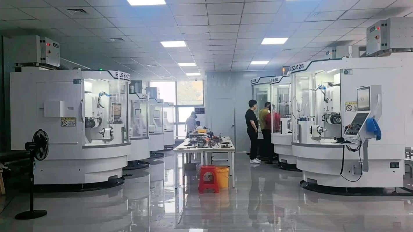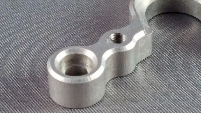
Electronics products are increasingly compact, powerful, and mechanically demanding. A modern electronics enclosure may need to protect a PCB, transfer heat away from processors, shield sensitive circuits from electromagnetic interference, locate connectors accurately, survive vibration, maintain environmental sealing, and still meet strict cosmetic requirements.
That combination makes the mechanical hardware around electronics much more important than it first appears.
A machined aluminum housing is not simply a protective box. Its base may act as a heat spreader. Its internal walls may separate RF sections. Its cover interface may provide an EMI shielding path. Precision bores may locate optical or sensing components. Connector cutouts must align with components already fixed to the PCB, while gasket grooves and sealing surfaces may determine whether the finished product survives dust, moisture, or outdoor use.
CNC machining is particularly useful for these parts because it combines design flexibility with production-grade materials and relatively tight dimensional control. Engineers can move from one prototype to dozens or hundreds of functional units without committing immediately to die-casting or injection-molding tooling.
This guide explains how CNC machining is used in the electronics industry, which parts are commonly machined, how materials and surface treatments affect performance, and what engineers should consider when designing enclosures, heat sinks, RF components, and other precision electronics hardware.
Why CNC Machining Is Widely Used for Electronics Hardware
Electronics development often moves much faster than conventional tooling.
PCB layouts change. Connector positions move. Display sizes are revised. Thermal loads increase after electronics testing. A new sensor may require a different mounting bore. A product that originally used a fan may be redesigned around passive cooling.
If the mechanical enclosure depends on expensive production tooling, every major design revision becomes slower and more expensive.
CNC machining avoids much of that problem because the part is produced directly from digital geometry. Changing the design usually means updating the CAD model and machining program rather than manufacturing an entirely new mold or die.
This makes CNC machining particularly valuable for:
- engineering prototypes;
- functional validation;
- EVT/DVT-style hardware builds;
- pilot production;
- low-volume commercial products;
- scientific instruments;
- industrial electronics;
- robotics controllers;
- communications equipment;
- specialized RF and optical hardware.
Unlike many additive prototypes, CNC-machined parts can also use the same aluminum, stainless steel, copper, brass, or engineering plastic that may be used in the final product.
That allows thermal, mechanical, assembly, and environmental testing to be performed on production-representative hardware.
1. CNC-Machined Electronics Enclosures
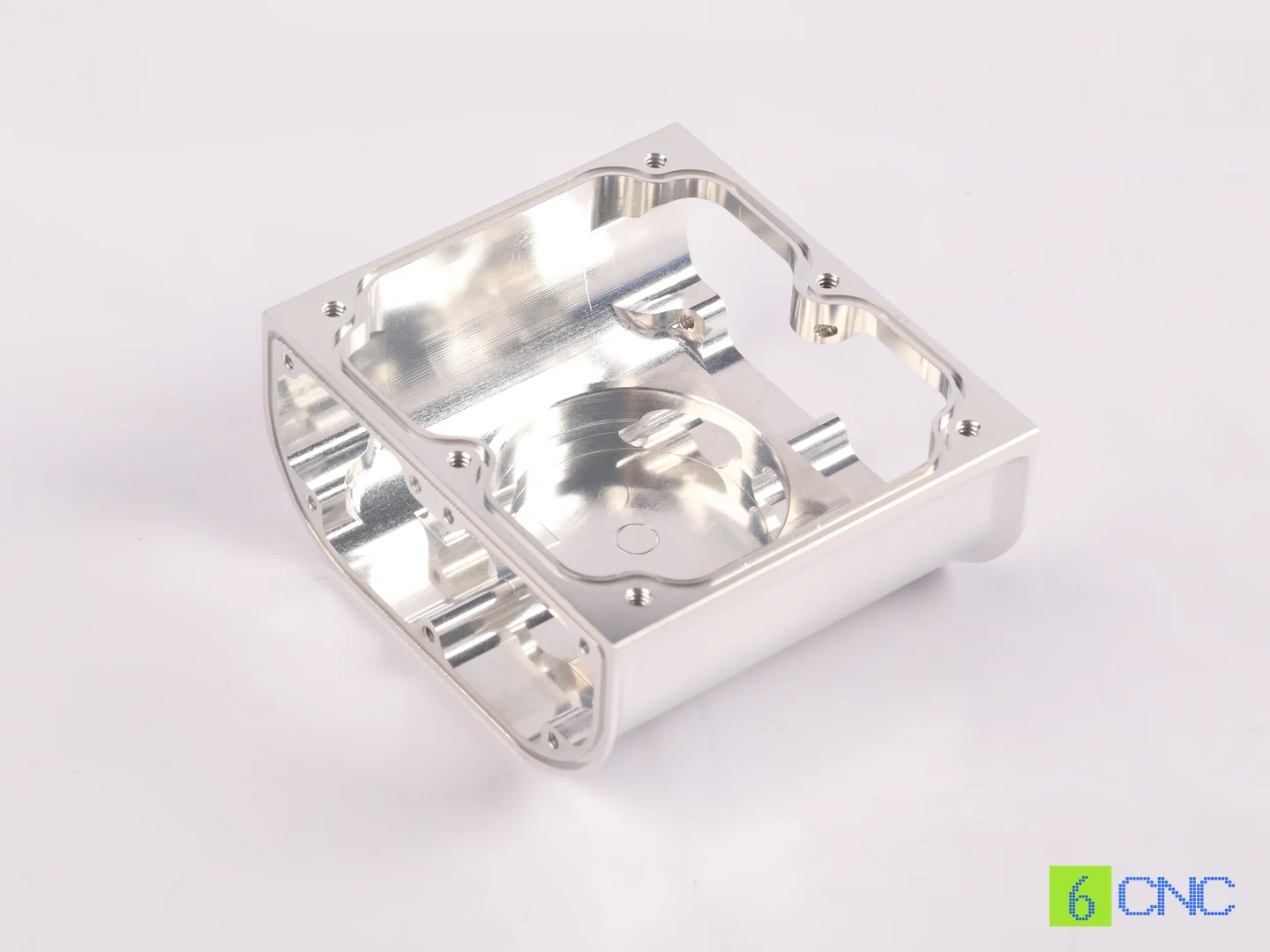
Enclosures are probably the most recognizable CNC-machined electronics components.
A typical machined enclosure may contain:
- internal PCB cavities;
- mounting standoffs;
- threaded holes;
- connector openings;
- display windows;
- button features;
- battery compartments;
- gasket grooves;
- grounding points;
- heat-sink fins.
Machining the enclosure from billet allows these features to be integrated directly into the structure.
This can reduce the number of separate brackets, standoffs, and heat-spreading components required during assembly.
Why Billet Aluminum Enclosures Are Popular
Aluminum 6061 is especially common because it combines relatively low weight, good machinability, useful thermal conductivity, corrosion resistance, and good anodizing behavior.
A machined aluminum enclosure can simultaneously provide:
- mechanical protection;
- structural rigidity;
- thermal conduction;
- electromagnetic shielding;
- mounting geometry.
That multifunctional behavior is difficult to reproduce with a basic plastic enclosure without adding separate thermal and shielding components.
For prototype and small-batch products, the absence of tooling also makes billet machining attractive even when the final high-volume product may eventually transition to die casting or extrusion.
Internal PCB Features
A good electronics enclosure usually needs more than a hollow cavity.
Internal geometry may include:
- PCB standoffs;
- card guides;
- locating pins;
- cable-routing channels;
- component clearance pockets;
- mounting bosses.
These features need to reflect the real PCB stack-up rather than approximate external dimensions.
For example, a board may fit perfectly inside the nominal cavity while a tall capacitor interferes with the cover.
Mechanical CAD should therefore incorporate the actual electronics geometry whenever possible.
2. Heat Sinks and Thermal Management Components
Heat is one of the most important mechanical problems in electronics.
Processors, power electronics, LEDs, RF amplifiers, batteries, and power supplies all generate heat. If that heat cannot leave the device effectively, component temperature rises and performance or reliability may suffer.
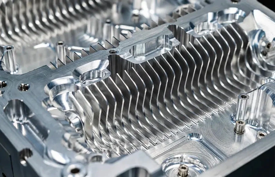
CNC machining can produce several types of thermal hardware:
- heat sinks;
- heat spreaders;
- cold plates;
- thermal baseplates;
- integrated finned enclosures.
Integrated Heat-Sink Enclosures
One useful approach is machining the enclosure and heat sink as one component.
Imagine a fanless industrial computer.
Instead of mounting a separate heat sink inside a box, the processor can transfer heat through a thermal interface material directly into a machined pedestal connected to the enclosure wall. Fins on the exterior then increase available surface area.
This removes several interfaces from the thermal path.
The structure may become:
processor → thermal interface material → aluminum enclosure → cooling fins
rather than:
processor → thermal pad → internal heat sink → interface → enclosure
Every additional interface adds thermal resistance and assembly variation.
Integrated thermal enclosures are therefore common in fanless electronics, robot controllers, outdoor computing hardware, and high-power embedded systems.
Thermal Interface Flatness
Heat-sink performance depends on more than fin size.
The surface contacting the heat source must also provide stable contact.
A warped or rough base can create localized gaps in the thermal interface.
For this reason, thermal mounting surfaces may have tighter requirements for:
- flatness;
- surface finish;
- coplanarity.
This is a good example of where a dimension that appears mechanically simple can directly affect electronic performance.
3. EMI and RFI Shielding Enclosures
Electronic systems can both generate and receive electromagnetic interference.
Metal enclosures help control this interference by providing a conductive shielding structure around sensitive circuitry.
But simply making the housing from aluminum does not automatically solve every EMI problem.
Shielding performance can also depend on:
- cover seams;
- conductive contact surfaces;
- gasket geometry;
- connector interfaces;
- grounding points;
- surface treatment.
Why Cover Interfaces Matter
A housing and cover may individually be conductive, but if their interface contains large gaps or electrically insulating coatings, the assembled shielding path can be compromised.
Designs may therefore use:
- tongue-and-groove joints;
- conductive gasket grooves;
- closely controlled mating surfaces;
- dedicated grounding pads.
The mechanical enclosure becomes part of the electrical design.
Anodizing Can Create an Electrical Problem
Anodizing is widely used on aluminum electronics housings because it improves appearance and corrosion resistance.
However, conventional anodized surfaces are electrically insulating.
That can be useful on some surfaces and undesirable on others.
If a designer expects a cover, grounding lug, or EMI gasket to make electrical contact directly through a fully anodized interface, the assembled part may not behave as expected.
Possible strategies include:
- selective masking before anodizing;
- removing coating from defined contact areas;
- using conductive conversion coatings;
- specifying appropriate plating.
This is why surface finishing should be decided together with EMI and grounding requirements rather than after machining is complete.
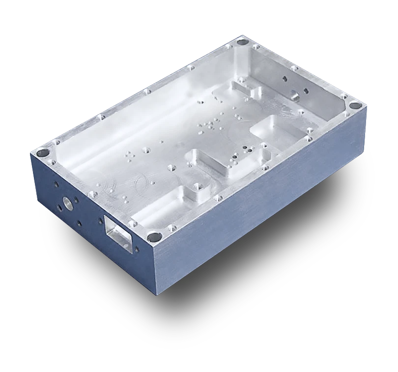
4. RF and Microwave Housings
RF and microwave electronics create even more demanding mechanical requirements.
Typical components include:
- RF cavity housings;
- filter bodies;
- amplifier housings;
- communication modules;
- radar electronics;
- satellite communication hardware.
These parts may contain several accurately machined cavities separated by thin walls.
The geometry is not simply structural.
Cavity dimensions can affect electromagnetic behavior.
Connector positions and internal surfaces may therefore require significantly more control than a conventional electronics box.
Surface Condition and Conductivity
RF components may require conductive finishes such as:
- chemical conversion coating;
- nickel plating;
- silver plating;
- other specified conductive treatments.
The correct finish depends on frequency, environmental exposure, electrical design, and customer requirements.
A finish should therefore never be selected purely for appearance.
Thin Internal Walls
RF cavity housings can contain relatively thin partitions between channels.
These walls may deform under:
- clamping force;
- cutting pressure;
- residual stress.
Machining strategy must preserve enough rigidity throughout roughing and finishing.
If a thin divider moves during cutting, the resulting cavity dimensions can change even when the CNC machine follows its programmed coordinates accurately.
5. CNC-Machined Heat Sinks
Standalone heat sinks are another important electronics application.
A machined heat sink may contain:
- baseplate;
- cooling fins;
- mounting holes;
- thermal contact surfaces;
- fan mounting features.
CNC machining is especially useful for prototype and specialized heat sinks where the fin pattern needs to match a particular device.
The Thin-Fin Machining Problem
Tall, thin fins are mechanically flexible.
As the cutter removes material between fins, each remaining fin becomes less rigid.
Aggressive cutting forces can push the fin away from the tool, resulting in:
- variable thickness;
- chatter;
- bent fins;
- poor surface finish.
Toolpath sequence therefore matters.
A machinist may remove material gradually between adjacent fins rather than completely freeing one very thin fin while the rest of the stock remains solid.
Copper heat sinks are even more demanding because copper combines excellent thermal conductivity with challenging machining behavior. Its ductility can contribute to burr formation and tool loading if tooling and cutting conditions are poorly selected.
6. Front Panels, Control Panels, and Display Frames
Electronics products often require machined front panels containing:
- screens;
- switches;
- buttons;
- LEDs;
- connectors;
- labels;
- countersunk fasteners.
These components combine dimensional and cosmetic requirements.
A connector hole that is slightly misplaced can interfere with PCB assembly. At the same time, visible machining marks on the front surface may make an otherwise functional product unacceptable.
For this reason, machining sequence often separates functional feature creation from final cosmetic finishing.
Engraving and Marking
CNC-machined panels may also contain:
- engraved text;
- serial-number locations;
- control labels;
- logos.
Alternatively, markings may be added after machining by laser engraving, screen printing, or another finishing process.
The manufacturing plan should consider how anodizing or coating affects the final appearance of those markings.
7. Connector Housings and Interfaces
Electronic connectors may appear small, but they often require accurate mechanical positioning.
Examples include:
- circular connector bodies;
- RF connector mounting interfaces;
- custom multi-pin connectors;
- cable gland features;
- sensor connectors.
Mechanical alignment matters because the machined housing must correspond to the PCB-mounted or cable-mounted connector.
If the panel opening is misaligned, assembly can place unwanted stress on the connector or board.
Typical machined requirements may include:
- bore position;
- thread quality;
- mounting-hole spacing;
- connector-face flatness.
For RF connectors, electrical contact and grounding can add another requirement.
8. Sensor and Camera Housings
Sensors and imaging systems often combine electronics with optical or precision mechanical interfaces.
A camera housing may need:
- a precision lens bore;
- sensor alignment features;
- O-ring groove;
- PCB mounting geometry;
- cable interface;
- black anodized internal surfaces.
In this case, the enclosure is not simply protecting electronics.
It is also controlling the relationship between the lens and sensor.
Bore position, perpendicularity, concentricity, or focus-related distances may therefore require tighter control than the general housing dimensions.
This is an area where 5-axis machining can sometimes reduce setup error because several optical and mounting features can remain related within one coordinate system.
9. PCB Test Fixtures and Electronics Manufacturing Tooling
Not every electronics-related CNC part ends up inside the finished product.
Electronics manufacturers use a large amount of custom tooling.
Examples include:
- PCB test fixtures;
- assembly nests;
- programming fixtures;
- connector alignment jigs;
- inspection fixtures;
- soldering fixtures.
These components are often required in very small quantities and may change whenever the PCB changes.
That makes CNC machining a natural manufacturing process.
A functional test fixture, for example, may need to locate a PCB precisely relative to pogo pins or connectors.
If the next PCB revision moves a connector 5 mm, modifying or remachining a fixture is relatively straightforward.
10. Semiconductor and High-Tech Electronics Equipment
Semiconductor manufacturing equipment uses many precision mechanical components even though the end products themselves are electronic.
Machined parts may include:
- equipment frames;
- vacuum-compatible fixtures;
- wafer-handling components;
- sensor mounts;
- precision plates;
- insulating polymer components.
Requirements may include:
- tight dimensional relationships;
- low contamination;
- specific surface finishes;
- vacuum compatibility;
- engineering plastics such as PEEK or PTFE.
These applications illustrate how broad the electronics category can become.
The CNC supplier may be machining hardware for the equipment that manufactures electronics rather than the consumer device itself.
Common Materials for Electronics CNC Machining
Material selection depends on whether the component primarily provides structure, thermal management, electrical conductivity, insulation, corrosion resistance, or appearance.
| Material | Typical electronics applications | Why it is used |
|---|---|---|
| Aluminum 6061 | Enclosures, heat sinks, frames, panels | Good machinability, thermal conductivity, anodizing |
| Aluminum 6063 | Heat-sink profiles, enclosures | Thermal performance and extrusion compatibility |
| Aluminum 7075 | High-strength structural electronics parts | Higher strength than 6061 |
| Copper C110 | Heat spreaders, thermal components | Very high thermal/electrical conductivity |
| Brass | Connectors, electrical hardware | Conductivity and machinability |
| Stainless steel | Rugged housings, brackets, hardware | Strength and corrosion resistance |
| PEEK | Electrical/thermal isolation, high-temperature parts | High-performance engineering polymer |
| POM/Delrin | Fixtures, insulators, low-friction parts | Good machinability and dimensional stability |
| PTFE | Electrical insulation and low-friction applications | Excellent dielectric and chemical properties |
Why Aluminum 6061 Is So Common
For general electronics housings, 6061 often provides the best balance of properties.
It is:
- relatively light;
- easy to machine;
- thermally conductive;
- structurally useful;
- corrosion resistant;
- suitable for anodizing.
7075 offers significantly higher strength but is not automatically the better enclosure material.
Many electronics housings do not need its additional strength, while 6061 is generally more attractive when thermal behavior, cost, machining, and finishing are considered together.
Copper for High-Performance Thermal Components
Copper provides substantially higher thermal conductivity than aluminum, making it attractive for:
- heat spreaders;
- cold plates;
- power electronics;
- high-heat-flux components.
However, copper is heavier and generally more difficult to machine cleanly.
It is therefore often used only where the thermal requirement justifies the additional material and machining cost.
Some assemblies combine both materials:
copper heat spreader + aluminum structure
This can provide high conductivity at the heat source while controlling overall weight and cost.
Engineering Plastics in Electronics
Not every electronics component should be metal.
Engineering plastics can provide:
- electrical insulation;
- RF transparency;
- chemical resistance;
- low weight;
- low friction.
PEEK may be used where high temperature, mechanical strength, and electrical insulation are needed.
POM/Delrin works well for many fixtures and mechanical insulating parts.
PTFE offers excellent electrical and chemical properties but requires additional care during precision machining because it is relatively soft and dimensionally sensitive.
Material selection should therefore follow the actual electrical and environmental requirement rather than defaulting automatically to aluminum.
Thermal Design Considerations for CNC-Machined Electronics
Thermal performance should be considered before mechanical design is finalized.
Several machining features can influence heat flow.
Thermal Contact Area
The surface transferring heat from an electronic component should provide enough contact area.
A very small pedestal may create a thermal bottleneck even if the rest of the housing is large.
Flatness
If the mating surface is warped, the thermal interface material must fill a larger gap.
That increases thermal resistance.
Fin Geometry
Fin thickness, spacing, height, and orientation affect cooling performance.
Extremely thin fins may look thermally attractive in CAD but become expensive or unstable to machine.
Airflow Direction
Fins should normally work with the expected airflow rather than being designed only around appearance.
Material Thickness
Reducing enclosure weight by making every wall extremely thin can also reduce heat-spreading capability and mechanical stiffness.
Thermal and mechanical optimization therefore need to happen together.
EMI Design Considerations for Machined Enclosures
A machined metal enclosure provides a useful starting point for EMI shielding, but the complete assembly determines real performance.
Engineers should consider:
- seam design;
- conductive contact;
- gasket position;
- connector grounding;
- surface treatment;
- screw spacing;
- aperture size.
A beautifully machined enclosure can still fail an EMC test if the cover and body do not establish an appropriate conductive path.
This is why the machine shop should know which surfaces are intended for electrical contact.
Those surfaces may need masking or a conductive finish instead of ordinary anodizing.
O-Ring Grooves and Environmental Sealing
Electronics used outdoors, in industrial environments, or around fluids may require sealed enclosures.
CNC machining can create accurate:
- face-seal grooves;
- radial O-ring grooves;
- gasket lands;
- sealing surfaces.
However, an O-ring groove should be designed around the actual seal geometry.
It is not simply a decorative rectangular channel.
The groove dimensions influence seal compression.
Surface condition also matters.
A sealing face containing deep cutter marks or discontinuities may leak even if the nominal dimensions are correct.
For sealed electronics hardware, the mechanical design may therefore need to manage EMI shielding, thermal transfer, and environmental sealing simultaneously.
That is one reason electronics enclosures can become surprisingly sophisticated machined components.
Thin-Wall Electronics Housings
Electronics designers naturally want smaller and lighter products.
That often leads to thin walls.
But thin-wall CNC machining creates several manufacturing challenges.
A wall may deform because of:
- clamping pressure;
- cutting force;
- residual material stress;
- heat.
Imagine machining a deep aluminum enclosure from billet.
At the beginning, the stock is extremely rigid.
As the internal cavity becomes deeper, the side walls become thinner and less supported.
Heavy finishing pressure may push a wall outward during cutting.
Once the tool moves away, the wall springs back.
The final dimension can therefore differ from the programmed toolpath.
Possible machining strategies include:
- balanced roughing;
- leaving temporary support material;
- staged wall finishing;
- lighter finishing passes;
- custom soft jaws;
- vacuum or specialized workholding.
A wall should therefore not be made thinner simply because the CAD software allows it.
Machining Deep Electronics Enclosures
Deep enclosures create another issue: tool reach.
The deeper the cavity, the longer the cutter must extend from the holder.
Long tool overhang reduces rigidity.
This increases the possibility of:
- chatter;
- tapered walls;
- poor surface finish;
- tool breakage.
Large internal corner radii can significantly improve manufacturability because they allow larger, more rigid cutters.
A very small internal radius in a deep electronics enclosure can force the use of a long, small-diameter end mill.
That combination increases both machining time and process risk.
Why 5-Axis Machining Can Help Electronics Parts
Many electronics housings do not require five-axis machining.
A relatively simple open enclosure can often be manufactured economically using 3-axis CNC milling.
Five-axis becomes valuable when the component contains:
- connector openings on several sides;
- angled ports;
- optical features;
- complex curved external geometry;
- deep features requiring better tool approach.
Imagine a robotics controller housing with connector faces on four sides.
A 3-axis process may require several separate setups.
A five-axis machine can potentially reach those faces while maintaining the component in one primary fixture.
This reduces handling and can improve the positional relationship between features.
The value of five-axis machining is therefore usually setup reduction and access, not simply because the component belongs to the electronics industry.
Surface Finishes for CNC-Machined Electronics Parts
Electronics parts often require surface finishing for appearance, corrosion protection, electrical function, or wear resistance.
Anodizing
Anodizing is common for aluminum housings.
It can provide:
- corrosion resistance;
- wear resistance;
- cosmetic appearance;
- color options.
Black anodizing is especially common for instruments, optical equipment, robotics, and electronics.
However, anodizing creates a nonconductive oxide layer and should be considered carefully around grounding and EMI interfaces.
Chemical Conversion Coating
Conversion coatings can provide corrosion protection while maintaining much better electrical conductivity than normal anodizing.
They are therefore useful for:
- grounding areas;
- EMI housings;
- internal RF surfaces.
Nickel Plating
Nickel plating can provide:
- a conductive surface;
- corrosion resistance;
- wear resistance.
It may be selected for RF or electrical components depending on the application.
Bead Blasting
Bead blasting creates a uniform matte cosmetic surface before anodizing or coating.
It is useful for appearance but should not be treated as a method for correcting dimensional or surface-flatness problems.
Surface Finish and Electrical Contact
Surface finish should be specified according to function.
An external cover may need a uniform cosmetic anodized appearance.
An internal grounding pad may need bare or conversion-coated aluminum.
A thermal contact face may need controlled flatness and roughness.
A sealing surface may need a finish suitable for the gasket or O-ring.
The same component can therefore require several different surface conditions.
This should be decided during design rather than after machining.
Tolerance Strategy for Electronics Components
Not every enclosure dimension requires tight tolerance.
Typical high-priority features include:
- precision connector locations;
- PCB mounting holes;
- optical bores;
- sealing grooves;
- thermal interfaces;
- dowel locations;
- mating cover surfaces.
Other external dimensions may tolerate significantly more variation.
Applying tight tolerances across the entire enclosure increases machining and inspection cost without necessarily improving product performance.
A better drawing separates:
function-critical dimensions
from
general geometry and cosmetic surfaces.
PCB-to-Housing Tolerance Stack-Up
A recurring electronics problem occurs when the PCB and enclosure are designed independently.
Consider a USB or circular connector soldered to a PCB.
Its final position depends on:
- PCB manufacturing tolerance;
- connector-placement tolerance;
- soldering;
- PCB mounting-hole tolerance;
- standoff position;
- machined housing opening.
If the housing cutout is designed with almost no clearance around the nominal connector position, assembly may become difficult even though each individual component is within its own drawing tolerance.
The complete tolerance stack should therefore be considered.
This is especially important for:
- board-mounted connectors;
- displays;
- switches;
- buttons;
- LEDs.
The machining supplier can control the metal part, but it cannot eliminate variation elsewhere in the assembly.
Cosmetic Requirements Can Increase Machining Cost
Electronics components are often visible to the customer.
This creates a manufacturing requirement that many purely industrial parts do not have.
A housing may be dimensionally correct but rejected because of:
- scratches;
- inconsistent tool marks;
- uneven bead blasting;
- visible fixture marks;
- anodizing differences.
Appearance surfaces should therefore be clearly identified on the drawing or manufacturing specification.
This allows the machine shop to plan:
- fixture contact locations;
- finishing passes;
- handling;
- packaging.
Otherwise, a surface treated as a normal machined face may unexpectedly become a cosmetic rejection issue.
CNC Machining vs Sheet Metal for Electronics Enclosures
CNC machining is not automatically the best process for every enclosure.
Sheet metal is often more economical for:
- large rectangular chassis;
- server enclosures;
- rack-mounted electronics;
- simple bent covers;
- higher-volume assemblies.
CNC machining becomes more attractive when the enclosure needs:
- deep integrated cavities;
- high rigidity;
- thermal conduction;
- tight connector positions;
- precision optical features;
- complex 3D geometry.
Some products combine the two.
A machined front panel or heat sink may be assembled with a folded sheet-metal chassis.
CNC Machining vs Die Casting
Die casting becomes attractive when a metal enclosure is produced at high volume.
It can create:
- thin walls;
- ribs;
- bosses;
- complex near-net geometry.
But tooling requires significant investment.
CNC machining is often more appropriate during:
- prototype development;
- design validation;
- pilot production;
- low-volume production.
As volume increases and the design stabilizes, a product may transition from:
billet CNC machining
to:
die casting + finish CNC machining.
Critical bores, sealing surfaces, threads, and connector features may still be machined after casting.
CNC Machining vs Extrusion
Extrusion is particularly useful for electronics products with constant cross-sectional geometry.
Examples include:
- amplifier housings;
- control modules;
- LED housings;
- long heat-sink enclosures.
The general cross-section can be extruded, then CNC machining creates:
- connector cutouts;
- mounting holes;
- threads;
- end features.
For repeat production, this can reduce material waste and machining time compared with removing the entire shape from billet.
CNC Machining vs 3D Printing for Electronics Hardware
3D printing is excellent for early enclosure prototypes.
It allows engineers to evaluate:
- basic shape;
- PCB fit;
- ergonomics;
- connector location.
However, printed polymer parts do not always reproduce the thermal conductivity, EMI shielding, rigidity, threads, or finish of the final metal component.
CNC machining is therefore commonly used when testing moves from appearance toward functional hardware.
An electronics project may progress through:
3D-printed concept model → CNC-machined functional prototype → CNC small-batch production → molded/cast production
depending on eventual volume.
Prototype to Small-Batch Electronics Manufacturing
Electronics development rarely jumps directly into high volume.
A typical project may require:
5 prototype housings
to verify fit.
Then:
30 engineering units
for electronics and thermal testing.
Then:
100 pilot-production units
for field evaluation.
Then:
300–500 units
for initial commercial production.
CNC machining works well during these stages because no dedicated mold is required.
The machining process can also mature as quantity increases.
Five prototypes may use relatively simple workholding.
A 300-piece order may justify:
- dedicated soft jaws;
- multi-part fixtures;
- probing;
- controlled tool-life limits;
- First Article Inspection;
- periodic dimensional checks.
This transition from prototype to repeatable small-batch production is especially important for electronics companies whose hardware continues evolving after the first functional unit.
Example: CNC-Machined Robotics Controller Housing
Consider a robotic controller housing machined from 6061 aluminum.
The component contains:
- deep electronics cavity;
- external cooling fins;
- four connector faces;
- internal PCB standoffs;
- O-ring groove;
- cover mounting holes.
The housing has three simultaneous jobs:
protect the electronics, remove heat, and provide environmental sealing.
The machining sequence might begin by establishing external datums and roughing the internal cavity.
Most material is removed while the part still has enough rigidity.
The side walls are then semi-finished.
Connector features on multiple faces may be machined using indexed 5-axis positioning to reduce setups.
The thermal contact area receives a controlled finishing pass.
The O-ring groove and cover interface are machined after the main geometry has stabilized.
Finally, the part is inspected and anodized, with any required grounding areas masked.
This is not just “machining an aluminum box.”
The mechanical manufacturing process directly affects thermal, electrical, assembly, and environmental performance.
Example: RF Electronics Housing
Consider an aluminum RF housing containing several internal cavities and SMA connector locations.
The critical requirements may include:
- cavity geometry;
- thin divider walls;
- connector position;
- cover mating surface;
- grounding contact.
The cavities are rough machined while leaving support around thin internal walls.
Semi-finishing creates consistent remaining stock.
A light final pass produces the functional geometry while minimizing wall deflection.
If the assembly requires electrical contact around the cover, the finishing specification must preserve conductivity at the mating interface.
The part may then receive a conductive conversion coating instead of fully insulating anodize on the relevant surfaces.
This example shows why machining and finishing need to be planned together.
Example: Optical Sensor Housing
A precision optical sensor housing may combine:
- electronics cavity;
- lens bore;
- sensor mount;
- connector holes;
- sealing groove.
The general enclosure dimensions may use standard machining tolerances.
The lens bore and sensor reference surfaces may require much tighter geometric control.
This is where the drawing should clearly identify the functional datum structure.
The manufacturing team can then focus inspection on the features that actually control optical alignment.
Quality Control for Electronics CNC Machining
Inspection requirements vary widely.
A simple front panel may require only normal dimensional inspection.
An optical or RF housing may require much more detailed verification.
Depending on the part, inspection may include:
- CMM;
- optical measurement;
- bore gauges;
- pin gauges;
- micrometers;
- calipers;
- surface roughness measurement;
- visual cosmetic inspection.
First Article Inspection becomes valuable before releasing larger small-batch orders.
This confirms that machining, surface finishing, and inspection methods are aligned before the complete batch is produced.
Design Tips for CNC-Machined Electronics Parts
A few design decisions can significantly improve manufacturability.
Use Practical Internal Corner Radii
Small internal corner radii require small cutters.
Deep geometry combined with small radii may require long, flexible tools.
Increasing the radius can reduce cycle time and improve surface quality.
Avoid Unnecessarily Thin Walls
Thin walls increase deformation risk.
Use thin geometry where weight or packaging requires it, not simply because it appears possible in CAD.
Design Connector Cutouts Around Real Assembly Tolerance
Do not assume the PCB connector will always sit exactly at nominal position.
Identify Thermal Contact Surfaces
Give these surfaces appropriate flatness and finish requirements.
Separate Conductive and Cosmetic Finishes
Mark grounding and EMI-contact areas clearly.
Use Standard Threads Where Possible
Unusual thread sizes can add tooling cost without improving product performance.
Consider Future Production
If the product may later use die casting or extrusion, early CNC versions can be designed with that transition in mind without sacrificing prototype flexibility.
How 6CNC Approaches Electronics CNC Machining
At 6CNC, electronics components are reviewed as functional mechanical systems rather than simply metal enclosures.
For prototype and small-batch projects, the manufacturing review can consider:
- PCB and connector interfaces;
- thermal surfaces;
- thin-wall geometry;
- EMI contact areas;
- sealing features;
- cosmetic surfaces;
- critical datums;
- machining access;
- expected production quantity.
Depending on the component, production can involve CNC milling, 5-axis machining, turning, mill-turn machining, precision grinding, Wire EDM, or complementary manufacturing processes.
Common materials include aluminum alloys, stainless steel, copper, brass, PEEK, POM, PTFE, and other engineering plastics.
Inspection can include CMM, optical measurement, gauges, micrometers, calipers, surface roughness testing, and material verification according to project requirements.
For small-batch electronics production, First Article Inspection and in-process checks can also help maintain consistency as the project moves from early engineering builds into repeated production orders.
The goal is not simply to machine the enclosure to its outside dimensions.
It is to manufacture the mechanical hardware so that the complete electronic assembly works as intended.
Final Thoughts
CNC machining is widely used in electronics because electronic hardware often demands more from its mechanical parts than basic structural support.
An enclosure may also be a heat sink.
A cover interface may also be an EMI seal.
A machined bore may determine optical alignment.
A side-wall opening may need to match a connector whose real position depends on an entire PCB tolerance stack.
These requirements make machining decisions part of the electronics design itself.
For prototype and small-batch production, CNC machining offers a particularly useful combination of flexibility, production-grade materials, precision, and low tooling investment. Designs can change quickly, real thermal and assembly behavior can be tested, and quantities can increase gradually without committing immediately to casting or molding.
As volume grows, the manufacturing route may eventually shift toward extrusion, die casting, sheet metal, or molding.
But even then, CNC machining often remains important for functional interfaces, critical holes, sealing surfaces, and final precision features.
If you are developing an electronics enclosure, heat sink, RF housing, sensor body, optical module, PCB fixture, or other precision electronics component, send 6CNC your CAD files, engineering drawings, material requirements, and expected quantities.
Our team can review the geometry for machinability, thermal and mechanical interfaces, critical tolerances, finishing requirements, and prototype-to-small-batch production.
Upload Your CAD Files → Request an Electronics CNC Machining Quote
Frequently Asked Questions
Why is CNC machining used for electronics enclosures?
CNC machining allows electronics companies to produce rigid, precise metal housings without dedicated tooling. Machined enclosures can also integrate heat sinks, PCB mounts, connector openings, EMI shielding features, and sealing geometry.
What is the best aluminum for electronics enclosures?
6061 is one of the most common choices because it offers good machinability, useful thermal conductivity, structural strength, corrosion resistance, and anodizing performance. 7075 may be selected where higher mechanical strength is required.
Can a CNC-machined aluminum enclosure provide EMI shielding?
Yes, a conductive metal enclosure can contribute strongly to EMI/RFI shielding. However, seams, conductive contact surfaces, gaskets, connector grounding, and surface finishes also affect the performance of the assembled enclosure.
Does anodizing affect electrical conductivity?
Yes. Conventional anodizing creates an electrically insulating oxide layer. Grounding or EMI contact surfaces may need masking, coating removal, or a conductive surface treatment depending on the design.
Can heat sinks be CNC machined?
Yes. CNC machining is useful for custom heat sinks, thermal baseplates, heat spreaders, and integrated heat-sink enclosures, particularly during prototypes and lower-volume production.
Why are thin electronics housings difficult to machine?
Thin walls can deflect under cutting or clamping forces. As the cavity is machined, the enclosure also loses rigidity. Machining sequence, fixture design, tool engagement, and finishing strategy therefore become important.
When is 5-axis machining useful for electronics parts?
Five-axis machining is useful when the enclosure contains features on multiple faces, angled connectors, complex contours, or deep geometry where changing tool orientation improves access and reduces setups.
Is CNC machining better than die casting for electronics housings?
For prototypes and low quantities, CNC machining usually avoids the tooling investment associated with die casting and allows faster design revisions. Die casting often becomes more economical as quantities increase and the design stabilizes.
Can copper electronics parts be CNC machined?
Yes. Copper is frequently machined for heat spreaders, electrical components, and thermal hardware. It offers excellent conductivity but generally requires more careful machining than aluminum.
What surface finishes are common for machined electronics parts?
Common finishes include anodizing, chemical conversion coating, nickel plating, bead blasting, powder coating, and as-machined surfaces. Finish selection should consider appearance, corrosion protection, electrical conductivity, thermal function, and grounding requirements.
What should I provide when requesting a quote for an electronics CNC part?
Provide the 3D CAD model, engineering drawing, material specification, quantity, surface treatment, critical dimensions, cosmetic requirements, and information about important thermal, sealing, EMI, grounding, or connector interfaces.