A hole can be the correct nominal diameter and still cause an assembly to fail.
It may be slightly off-position.
It may not be round enough.
Two bearing bores may not share the same axis.
A deep bore may taper from one end to the other.
Or a drilled hole may simply be too rough or inaccurate for the shaft, bearing, bushing, piston, or precision insert that must fit inside it.
This is where CNC boring becomes important.
Boring is a machining process used to enlarge, correct, and finish an existing hole using a cutting tool.
Unlike drilling, boring normally starts with a hole that already exists.
That initial hole may have been created by:
- Drilling
- Casting
- Forging
- Milling
- Core machining
- Another rough-machining operation
The purpose of boring is to bring that hole closer to its final:
- Diameter
- Position
- Roundness
- Straightness
- Alignment
- Surface finish
Modern CNC boring services are used across precision machining, aerospace, automotive, robotics, energy, hydraulic equipment, industrial machinery, and many other applications where hole geometry matters as much as hole size.
But boring is not always the final operation.
A bore may be:
Drilled → Bored → Reamed
or:
Drilled → Bored → Honed
or simply:
Rough Bored → Finish Bored
The correct process depends on what the finished hole actually needs to do.
This guide explains how CNC boring works, how it differs from drilling, reaming, and honing, what controls the accuracy of a bored hole, and how engineers should design and specify tight tolerance bores. For examples of how materials, sealing interfaces and inspection shape the process, read our guide to CNC machining in the energy industry.
What Is CNC Boring?
CNC boring is a precision machining process used to enlarge and refine an existing hole.
A single-point or adjustable boring tool removes material from the internal diameter until the required geometry is achieved.
The operation may be performed on:
- CNC lathes
- CNC milling machines
- Machining centers
- Horizontal boring mills
- Vertical boring mills
- Multi-task machines
The exact machine configuration depends on the workpiece.
For example:
A cylindrical part may be bored on a CNC lathe.
A housing containing several precision bearing bores may be machined on a 3-axis, 4-axis, or 5-axis machining center.
A very large machine frame or gearbox housing may require a horizontal boring service.
The cutting principle remains similar, but the way the tool and workpiece move can be very different.
What Is the Main Purpose of Boring?
The main purpose is not simply to make a hole larger.
Boring gives the machining process greater control over the final geometry of an existing hole.
It may be used to improve:
- Bore diameter
- Hole position
- Roundness
- Straightness
- Coaxiality
- Concentricity-related requirements
- Cylindricity
- Surface finish
This is why boring is common on functional internal diameters.
Typical examples include:
- Bearing bores
- Bushing bores
- Gearbox housings
- Valve bodies
- Cylinder bores
- Hydraulic components
- Spindle housings
- Motor housings
- Pump bodies
- Precision sleeves
These holes normally do more than provide clearance.
They locate, guide, support, seal, or align another component.
How Does CNC Boring Work?
The exact boring process depends on whether the workpiece or the cutting tool rotates.
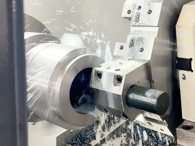
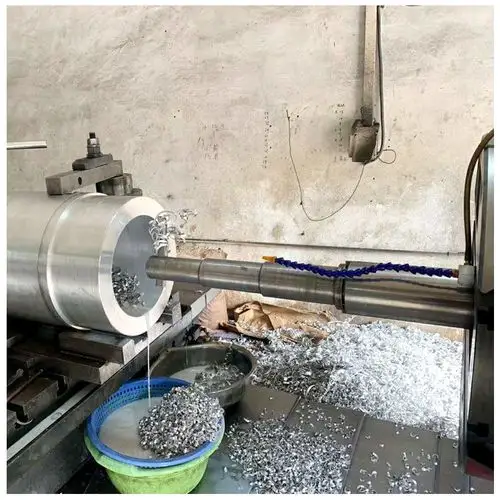
Boring on a CNC Lathe
On a lathe:
The workpiece rotates.
A boring bar enters an existing hole and moves along the inside diameter.
This is commonly called:
- Internal turning
- ID turning
- Boring
It is well suited to rotational parts such as:
- Sleeves
- Bushings
- Cylinders
- Rings
- Pulleys
- Hubs
- Flanges
The bore is naturally related to the rotational axis established by the machine setup.
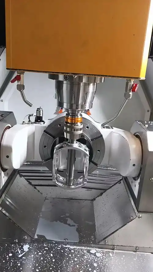
Boring on a CNC Milling Machine
On a machining center:
The cutting tool rotates.
The workpiece remains clamped to the machine table or fixture.
A boring head or boring tool rotates inside the existing hole.
This is useful for parts such as:
- Housings
- Machine frames
- Manifolds
- Gearboxes
- Structural components
The CNC machine controls where the bore is located relative to other part features.
This makes boring especially valuable when bore position is critical.
Why Not Just Use a Drill?
Drilling is excellent at creating holes quickly.
But a drill is not always the best tool for establishing the final geometry of a precision bore.
A drilled hole may contain:
- Diameter variation
- Position error
- Runout
- Poor roundness
- Surface irregularities
- Tool wandering
These effects become increasingly important as:
- Hole depth increases
- Diameter increases
- Tolerance becomes tighter
- Material becomes difficult to machine
A boring tool removes material from the already-existing hole and gives the machine greater control over the final internal surface.
This is why a precision machining sequence may look like:
Drill Ø19.5 mm → Bore Ø19.9 mm → Finish Bore Ø20.000 mm
rather than trying to create the final precision diameter directly with a Ø20 mm drill.
CNC Boring vs. Drilling
Boring and drilling are closely related but serve different purposes.
| Feature | Drilling | CNC Boring |
|---|---|---|
| Main purpose | Create a hole | Enlarge/refine an existing hole |
| Tool | Drill | Boring bar or boring head |
| Existing hole required | No | Yes |
| Hole positioning | Good | Can improve an existing bore |
| Diameter control | Moderate to good | Higher |
| Roundness control | Moderate | Better |
| Adjustable diameter | Limited | Highly controllable |
| Surface finish | Moderate | Better |
| Typical role | Rough hole creation | Precision machining |
In many precision parts, drilling and boring are therefore used together.
Drilling creates the initial opening.
Boring establishes the precision geometry.
What Is Precision Boring Machining?
Precision boring machining refers to boring operations where dimensional and geometric control is the primary objective rather than simply removing material.
The process may focus on characteristics such as:
- Final bore diameter
- Bore location
- Roundness
- Cylindricity
- Straightness
- Alignment with another bore
- Perpendicularity to a face
- Surface finish
Precision boring is commonly used for:
- Bearing seats
- Gearbox housings
- Spindle bores
- Hydraulic components
- Valve bodies
- Precision equipment housings
It is particularly useful when the relationship between the bore and other part features matters.
Rough Boring vs. Finish Boring
Boring is often divided into two stages.
Rough Boring
Rough boring removes most of the remaining material.
The priorities are:
- Material removal
- Tool stability
- Preparing consistent stock
- Correcting large initial errors
The bore is intentionally left slightly undersize for finishing.
Finish Boring
Finish boring removes the final allowance.
The priorities shift toward:
- Diameter
- Geometry
- Surface finish
- Repeatability
Finish cuts usually remove much less material.
However, an extremely tiny finishing cut is not automatically better.
If the depth of cut becomes too small relative to:
- Insert edge radius
- Material behavior
- Tool deflection
the tool may rub or behave unpredictably rather than cutting cleanly.
Process planning must therefore leave an appropriate and consistent finishing allowance.
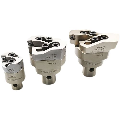
What Is a Fine Boring Head?
On machining centers, precision bores are often produced using adjustable fine-boring heads.
Unlike a fixed-diameter drill, a fine-boring tool can be adjusted in very small increments.
This allows the machinist to compensate for:
- Tool wear
- Actual measured bore size
- Thermal effects
- Batch variation
A typical workflow may be:
- Machine the rough bore
- Take a semi-finish boring pass
- Measure the bore
- Adjust the boring head
- Perform the final finishing pass
- Inspect the finished diameter
This makes fine boring particularly useful for tight tolerance bores.
Why Boring Can Correct Hole Position Better Than Reaming
This is an important difference.
A reamer generally follows the existing hole.
If the hole is significantly out of position, simply pushing a reamer through it will not necessarily relocate the bore correctly.
A rigid boring operation can remove material selectively from the internal surface.
This gives boring a greater ability to establish the bore according to the machine spindle axis.
For a housing where bore position relative to datums is critical, boring can therefore be preferable before final reaming or honing.
Tight Tolerance Bores
The phrase tight tolerance bore can refer to several different requirements.
It may mean:
- Tight diameter tolerance
- Tight roundness
- Tight cylindricity
- Accurate bore location
- Precise alignment between multiple bores
- Tight perpendicularity
- Controlled surface finish
These should not be treated as the same thing.
A bore can meet its diameter tolerance and still fail another functional requirement.
Diameter Is Only One Part of Bore Accuracy
Consider a bore specified as:
Ø25.000 ±0.005 mm
A machinist may measure:
25.002 mm
and conclude that the diameter is acceptable.
But what if the bore is:
- 25.000 mm near the entrance
- 25.004 mm in the middle
- 25.008 mm at the back
The bore may have taper.
Or perhaps two measurements taken at 90 degrees show:
- 24.999 mm
- 25.006 mm
The bore may have roundness error.
A single diameter reading cannot fully describe bore geometry.
Roundness
Roundness controls how closely each circular cross-section approaches a perfect circle.
Poor roundness may affect:
- Bearings
- Pistons
- Valve spools
- Bushings
- Precision sliding fits
Possible causes include:
- Tool deflection
- Chatter
- Workpiece distortion
- Poor machine stability
- Interrupted cuts
Boring can produce good roundness, but exceptionally demanding requirements may require additional processes such as honing or internal grinding.
Cylindricity
Cylindricity controls the overall three-dimensional form of the bore.
It effectively considers how accurately the entire cylindrical surface maintains the intended geometry.
This can matter in:
- Long bearing bores
- Precision sleeves
- Hydraulic components
- Spindle housings
A part can have an acceptable diameter at several measured locations but still fail a strict cylindricity requirement.
Bore Straightness
Long bores are particularly sensitive to straightness.
The deeper the boring tool enters the workpiece, the more difficult it becomes to maintain tool rigidity.
Possible errors include:
- Taper
- Curvature
- Diameter drift
- Chatter
Tool length therefore becomes one of the most important variables in deep boring.
Bore Position
In housing-type components, the center of the bore may need to be positioned accurately relative to:
- Datum surfaces
- Mounting holes
- Another bore
- A machined face
- A gear centerline
This requirement may be specified using GD&T position controls.
A perfectly sized bore in the wrong position is still a defective feature.
Coaxial Bores
Many components contain two or more bores that must share a common axis.
Examples include:
- Gearbox housings
- Bearing housings
- Machine frames
- Robotic joints
- Motor housings
This creates a different machining problem from simply holding each bore diameter.
If the bores are machined in separate setups, setup error can affect their relationship.
Whenever practical, machining critical coaxial bores in the same setup can reduce accumulated alignment error.
Boring Bar Deflection: The Main Challenge in Internal Machining
One of the biggest technical challenges in CNC bore machining is boring-bar deflection.
A boring bar behaves like a cantilever beam.
The tool is supported at one end.
The cutting edge extends into the bore.
Cutting forces push against the cutting tip.
As the unsupported length increases, the tool becomes easier to bend.
This can produce:
- Oversize or undersize bores
- Taper
- Chatter
- Poor surface finish
- Unstable tool life
For this reason, one fundamental boring rule is:
Keep the boring bar as short and as large in diameter as the geometry allows.
Why Boring Bar Length Matters So Much
Imagine two boring bars with the same diameter.
One extends:
30 mm
from the holder.
The other extends:
120 mm.
The longer bar will be dramatically less rigid.
Even though the cutting tool, material, and machine are identical, the second setup may behave completely differently.
This is why boring becomes increasingly difficult as the bore depth-to-diameter ratio increases.
Length-to-Diameter Ratio in Boring
Boring-tool stability is often discussed using:
L/D ratio
where:
- L = unsupported tool length
- D = boring-bar diameter
Lower L/D generally means greater rigidity.
For conventional boring bars, keeping the overhang close to roughly 4× bar diameter or less is a common starting guideline.
Longer reaches may require:
- Carbide boring bars
- Heavy-metal bars
- Damped boring bars
- Specialized anti-vibration tooling
The actual usable overhang depends on the complete cutting system.
Steel vs. Carbide Boring Bars
Steel Boring Bars
Advantages include:
- Lower cost
- Good general-purpose performance
- Wide availability
They work well for relatively short overhangs.
Carbide Boring Bars
Carbide has greater stiffness than steel.
This can improve stability when longer reach is required.
Potential benefits include:
- Reduced deflection
- Improved finish
- Better dimensional consistency
The tradeoff is higher tooling cost and greater brittleness.
Damped Boring Bars
For very long internal machining operations, manufacturers may use vibration-damped boring bars.
These tools contain an internal damping system designed to absorb vibration.
They are especially useful for:
- Deep bores
- Long overhangs
- Large housings
- Difficult internal turning
They do not eliminate the need for correct cutting parameters, but they can extend the range in which stable boring is possible.
Why a Larger Boring Bar Is Better
If two boring bars can reach the same feature, the larger-diameter bar will normally provide greater rigidity.
That is why bore geometry should allow the largest practical bar.
A small opening may force the use of a thin bar.
This becomes particularly problematic if the hole is also very deep.
The combination:
Small Bore + Long Depth
is substantially more difficult than:
Large Bore + Short Depth
even when both require the same diameter tolerance.
Tool Overhang and Bore Design
This has an important DFM implication.
Suppose a designer specifies:
- Ø10 mm bore
- 80 mm depth
- Tight diameter tolerance
- Fine surface finish
The tool may require an extremely high L/D ratio.
That changes the manufacturing difficulty dramatically.
If the design can instead use:
- Larger access diameter
- Shorter critical bore
- Two-sided machining
- Counterbore
- Different component architecture
manufacturability can improve substantially.
What Causes Chatter During Boring?
Chatter is a self-excited vibration between:
- Cutting tool
- Workpiece
- Machine
It commonly produces a repeating pattern on the internal surface.
Symptoms may include:
- Loud machining noise
- Visible waves
- Poor finish
- Diameter instability
- Rapid insert wear
Common causes include:
- Excessive boring-bar overhang
- Small bar diameter
- Weak workholding
- Incorrect cutting parameters
- Excessive tool nose radius
- Machine vibration
- Thin workpiece walls
Deep boring is particularly sensitive.
How to Reduce Boring Chatter
Possible strategies include:
Reduce Tool Overhang
Usually the first and most effective action.
Increase Boring-Bar Diameter
Use the largest bar permitted by the bore.
Improve Workholding
The workpiece must be as stable as the tool.
Change Cutting Speed
Moving away from a resonant frequency can reduce vibration.
Adjust Feed and Depth of Cut
Very light cutting is not always the most stable condition.
Use a Smaller Nose Radius
A large nose radius can increase radial cutting forces.
Use a Carbide or Damped Bar
Especially for deep internal machining.
The correct solution depends on the specific boring operation.
Boring and Tool Nose Radius
The insert nose radius influences:
- Cutting forces
- Surface finish
- Edge strength
A larger nose radius can theoretically support a smoother finish under appropriate feed conditions.
But it also produces greater radial cutting force.
During deep boring, this can increase:
- Deflection
- Vibration
- Chatter
This is why finishing parameters cannot be selected by surface-finish theory alone.
Tool stability must also be considered.
Cutting Speed in CNC Boring
Cutting speed depends on:
- Workpiece material
- Tool material
- Insert coating
- Bore diameter
- Stability
- Coolant condition
Because the cutting edge works inside the component, chip control and heat removal can be more difficult than on an external turning operation.
Excessive speed may increase:
- Tool wear
- Heat
- Built-up edge
- Dimensional drift
The correct cutting speed therefore depends on both material and boring geometry.
Feed Rate in Boring
Feed affects:
- Surface finish
- Chip formation
- Tool pressure
- Cycle time
Very high feed can produce:
- Rougher surface
- Increased cutting force
Extremely low feed can create:
- Rubbing
- Unstable chip formation
- Poor tool behavior
The correct feed must match:
- Insert geometry
- Nose radius
- Material
- Depth of cut
Chip Control Inside a Bore
Chip evacuation is more difficult inside a hole than on an exposed external surface.
Poor chips may:
- Wrap around the boring bar
- Scratch the finished bore
- Block coolant
- Damage the insert
- Become trapped in blind holes
This is particularly challenging in:
- Deep holes
- Blind bores
- Ductile materials
- Small-diameter bores
Insert chipbreaker, feed, coolant, and tool orientation all affect chip evacuation.
Through Bores vs. Blind Bores
Through Bore
A through bore passes completely through the workpiece.
Advantages may include:
- Easier chip evacuation
- Better tool access
- Easier coolant flow
Blind Bore
A blind bore stops inside the component.
Blind boring introduces additional challenges.
The tool must control:
- Final diameter
- Bore depth
- Bottom geometry
- Chip evacuation
Chips have fewer paths to escape.
This increases the importance of chip control and coolant.
Stepped Bores
A stepped bore contains multiple internal diameters.
For example:
Ø30 → Ø25 → Ø20
These features may locate:
- Bearings
- Seals
- Bushings
- Retaining components
The machining plan must consider:
- Tool access
- Shoulder geometry
- Diameter relationships
- Depth
- Inspection
A CNC lathe can often produce several concentric internal diameters in one setup.
This is valuable when their relationship is critical.
Back Boring
Sometimes the critical surface is located on the back side of a feature and cannot be approached conveniently from the normal direction.
Back boring allows the cutter to machine a rear-facing internal surface after passing through an opening.
Applications may include:
- Counterbores
- Rear spot faces
- Difficult shoulders
Special tooling and adequate clearance are required.
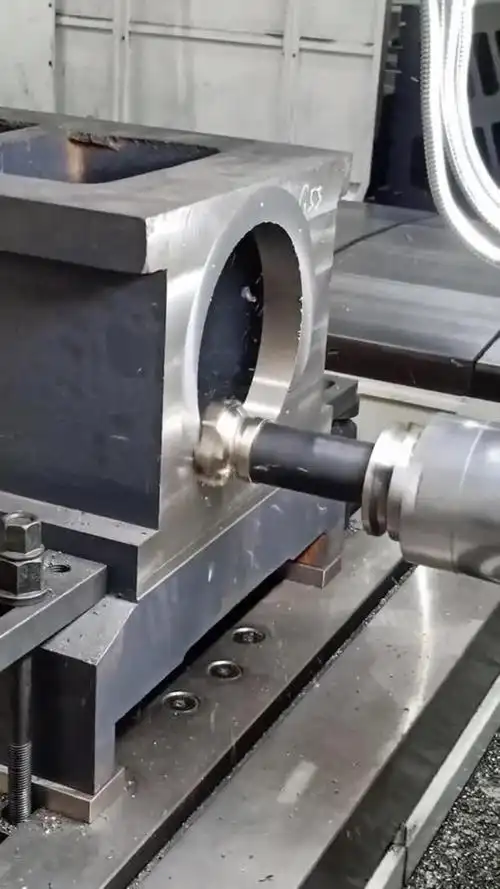
Horizontal Boring
A horizontal boring machine uses a horizontally oriented spindle and is particularly valuable for large workpieces.
Typical parts include:
- Large gearbox housings
- Machine-tool structures
- Heavy equipment frames
- Pump housings
- Energy equipment
- Large bearing housings
Instead of moving a very large component through multiple conventional machines, a horizontal boring mill can perform several operations in one setup.
These may include:
- Boring
- Milling
- Drilling
- Facing
- Tapping
When Is a Horizontal Boring Service Useful?
A horizontal boring service becomes attractive when the workpiece is:
- Large
- Heavy
- Difficult to reposition
- Contains deep bores
- Requires bores on multiple sides
- Requires accurate relationships between distant features
The major advantage is not simply bore diameter.
It is the ability to establish multiple large precision features relative to the same setup.
Horizontal Boring vs. Horizontal Machining Center
The boundary between modern horizontal boring mills and horizontal machining centers can overlap.
A traditional horizontal boring mill is particularly associated with:
- Large work envelopes
- Heavy components
- Extendable boring spindles
- Deep internal features
Horizontal machining centers tend to emphasize:
- Automated production
- Pallet systems
- High spindle speeds
- Multi-face machining
The correct machine depends on:
- Component size
- Bore depth
- Required accuracy
- Production quantity
Line Boring
Line boring is used when multiple bores must share a common axis.
A boring bar passes through two or more bearing locations.
Common applications include:
- Heavy machinery
- Excavator arms
- Engine blocks
- Large gearbox housings
- Machine frames
Line boring is also frequently used for repairing worn bores on large equipment.
It should not be confused with ordinary single-hole CNC boring.
CNC Boring vs. Reaming
Reaming is another common precision-hole process.
A reamer contains multiple cutting edges and removes a relatively small amount of material.
| Feature | Boring | Reaming |
|---|---|---|
| Tool type | Usually single-point | Multi-edge |
| Diameter flexibility | High | Fixed or limited |
| Hole position correction | Better | Limited |
| Stock removal | Moderate | Low |
| Productivity | Moderate | High |
| Surface finish | Good | Very good |
| Best use | Geometry correction/flexible sizing | Repeated finishing of prepared holes |
For many production holes:
Drill → Bore → Ream
can be an effective sequence.
But not every bore requires reaming.
A correctly controlled finish-boring operation may already meet the drawing requirement.
CNC Boring vs. Honing
Boring and honing serve different purposes.
Boring
Uses a defined cutting edge.
Best for:
- Establishing diameter
- Correcting position
- Removing more stock
- Establishing basic bore geometry
Honing
Uses abrasive stones.
Best for refining:
- Roundness
- Cylindricity
- Straightness
- Surface texture
A precision hydraulic bore may therefore use:
Drilling → Boring → Honing
The boring operation establishes the bore.
The honing operation performs the final fine correction.
Boring vs. Internal Grinding
Internal grinding uses an abrasive wheel instead of a cutting insert.
It is particularly useful for:
- Hardened materials
- Heat-treated components
- Very fine finishing
- Precision bores
Boring is generally more flexible for material removal and geometry generation.
Internal grinding becomes attractive when:
- Material is hardened
- Surface finish is extremely demanding
- Final geometric requirements favor grinding
The two processes may also be used sequentially.
Boring vs. Circular Interpolation Milling
Modern CNC machining centers can create large holes by circular interpolation.
An end mill follows a circular toolpath.
This is flexible because one cutter can produce multiple diameters.
However, circular interpolation and boring are not identical.
For highly critical bores, a precision boring tool may provide advantages in:
- Roundness
- Surface continuity
- Diameter adjustment
- Process predictability
Circular interpolation remains excellent for:
- Roughing bores
- Large diameter holes
- Flexible prototype machining
- Noncritical internal features
A common strategy is:
Helical/Circular Mill the Rough Hole → Finish Bore
Boring vs. Jig Boring
Jig boring historically developed for extremely accurate hole location.
Jig borers emphasized:
- Positional accuracy
- Precision coordinate movement
- Accurate bores
Modern precision CNC machining centers have taken over many applications that previously required dedicated jig boring machines.
However, the fundamental requirement remains:
The bore must be both the correct size and in the correct location.
Materials Suitable for CNC Boring
Boring can be performed on many machinable engineering materials.
Aluminum
Aluminum is generally favorable for boring.
Common grades include:
- 6061
- 6063
- 7075
- 2024
- 6082
Advantages include:
- High cutting speeds
- Relatively low cutting forces
- Good machinability
Potential issues include:
- Built-up edge
- Chip control
- Thin-wall distortion
Sharp tooling is particularly important.
Stainless Steel
Common grades include:
- 304
- 316
- 416
- 420
- 17-4 PH
Austenitic stainless steels can be more difficult because they may:
- Work harden
- Generate significant heat
- Produce difficult chips
Tool engagement should remain consistent.
Carbon and Alloy Steel
Common examples include:
- 1018
- 1045
- 4140
- 4340
These are widely used in:
- Housings
- Mechanical equipment
- Hydraulic parts
- Automotive components
Tooling and cutting conditions depend strongly on hardness.
Cast Iron
Cast iron is commonly bored in:
- Engine components
- Pump housings
- Gearboxes
- Machine structures
It generally machines well with appropriate tooling but creates abrasive particles and dust that must be managed correctly.
Titanium
Titanium boring requires more conservative cutting conditions.
Challenges include:
- Heat concentration
- Tool wear
- High cutting forces
Internal tool stability becomes especially important.
Engineering Plastics
Materials such as:
- POM
- PEEK
- Nylon
- PTFE
can also contain precision bores.
However, plastic parts introduce different problems.
They may experience:
- Elastic recovery
- Heat-related dimensional change
- Clamping deformation
- Burrs
A measured bore immediately after machining may not behave exactly like a metal bore.
Boring Thin-Walled Components
Thin-walled housings require special attention.
Imagine a thin aluminum housing clamped tightly in a fixture.
The fixture distorts the bore area slightly.
The machine then finish-bores the hole perfectly round.
When the clamp is released, the housing relaxes.
The bore may no longer be round.
This is not necessarily a machine-accuracy problem.
It is a workholding problem.
Solutions may include:
- Reduced clamping force
- Better support
- Custom soft jaws
- Machining in a representative assembly condition
- Rough and finish machining in separate stages
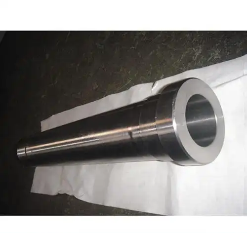
Deep Bore Machining
Deep bores are more difficult because every extra millimeter of tool extension reduces rigidity.
Challenges include:
- Tool deflection
- Chatter
- Chip evacuation
- Coolant delivery
- Measurement
- Taper
The machining strategy may require:
- Carbide boring bars
- Vibration-damped bars
- Multiple passes
- Reduced cutting forces
- Through-tool coolant
At some depth, a different process may be more suitable than conventional boring.
Large-Diameter Boring
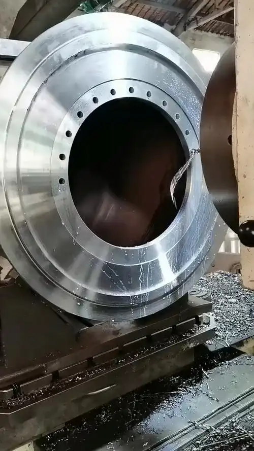
Large bores create a different set of challenges.
Typical applications include:
- Turbine housings
- Gearboxes
- Large bearing seats
- Industrial equipment
- Energy equipment
The machine must provide:
- Sufficient travel
- Adequate spindle power
- Stable workholding
- Accurate boring-tool adjustment
For very large parts, moving the workpiece itself may become one of the major manufacturing constraints.
Horizontal boring equipment is often valuable for this reason.
Small-Diameter Boring
Small bores may require very slender boring tools.
As bore diameter decreases, there is less room for:
- Tool body
- Chip evacuation
- Coolant
This makes miniature boring especially sensitive to:
- Runout
- Tool rigidity
- Chip control
In very small holes, alternative processes may be more practical depending on tolerance and depth.
How Accurate Can CNC Boring Be?
There is no meaningful universal tolerance for all bored holes.
Capability depends on:
- Bore diameter
- Bore depth
- Workpiece material
- Machine rigidity
- Tool overhang
- Part stiffness
- Temperature
- Required geometry
- Inspection method
A shallow Ø50 mm bore in a rigid steel housing and an Ø8 mm × 100 mm deep bore are completely different machining problems.
Both may be described as “precision boring.”
Therefore, capability should always be evaluated from the complete feature geometry.
Tight Diameter Tolerance vs. Tight Geometric Tolerance
This distinction is critical.
Suppose two drawings both specify:
Ø40.000 ±0.005 mm
Part A requires no additional geometry.
Part B also specifies:
- Position 0.01 mm
- Cylindricity 0.005 mm
- Perpendicularity to datum A
- Ra 0.4 μm
Part B is substantially more difficult.
The diameter tolerance alone does not describe the manufacturing challenge.
Bore Surface Finish
Surface finish in boring is influenced by:
- Feed
- Nose radius
- Insert geometry
- Cutting speed
- Vibration
- Material
- Tool wear
A stable finish-boring process can produce a very good surface.
But extremely fine surfaces may be better produced by:
- Reaming
- Honing
- Internal grinding
depending on the application.
The correct process should be based on function rather than pursuing the smallest possible Ra value.
Bearing Bores
Bearing bores are among the most common precision-boring applications.
The bore may control:
- Bearing fit
- Alignment
- Gear position
- Shaft performance
- Bearing life
Important drawing requirements can include:
- Diameter
- Fit
- Roundness
- Cylindricity
- Bore position
- Alignment between bearing seats
For a gearbox with two bearings supporting one shaft, the relationship between the two bearing bores may matter as much as the diameter of either individual hole.
Bushing Bores
Some components use a machined bore to accept a press-fit bushing.
The housing bore therefore needs:
- Correct diameter
- Sufficient roundness
- Appropriate surface condition
After the bushing is installed, its inside diameter may require additional finishing.
This can include:
- Reaming
- Boring
- Honing
Press-fitting the bushing can change its internal diameter.
Therefore, the final bushing ID should sometimes be machined after installation.
Hydraulic and Valve Bores
Hydraulic components may contain bores for:
- Spools
- Pistons
- Sleeves
- Valves
These applications may require combinations of:
- Diameter accuracy
- Straightness
- Roundness
- Fine surface texture
Boring is often an intermediate precision step.
Final honing may then establish the finished functional bore.
Motor and Gearbox Housings
These are particularly important boring applications.
A housing may contain several bearing bores that must maintain accurate relationships.
Critical characteristics include:
- Bore location
- Coaxiality
- Center distance
- Perpendicularity
- Diameter
Whenever practical, critical bores should be machined from a common setup or through a process specifically designed to maintain their datum relationship.
Robotics and Automation Components
Robotic joints, actuator housings, and automation equipment often contain:
- Bearing bores
- Gearbox bores
- Motor locating features
- Precision pivot bores
The bore may control the alignment of several mechanical systems simultaneously.
For these parts, the correct manufacturing plan should consider:
Bore size + Bore position + Datum structure + Assembly function
rather than only the nominal diameter.
Aerospace Components
Aerospace structures and systems may contain precision bores for:
- Bearings
- Bushings
- Actuators
- Hydraulic components
- Structural joints
Requirements may include close control of:
- Position
- Diameter
- Surface finish
- Traceability
Material machinability can also vary significantly between:
- Aluminum
- Titanium
- Stainless steel
- High-strength alloys
How Should Precision Bores Be Specified on Drawings?
A drawing should define the functional result.
Do not simply write:
PRECISION BORE
That does not tell the manufacturer what matters.
Bore Diameter
Specify the final diameter and tolerance.
For example:
Ø25.000 ±0.005 mm
or an appropriate ISO fit.
Fits
For bearing and shaft assemblies, ISO fit systems may communicate the requirement more effectively.
Examples include:
- H6
- H7
- H8
The correct fit depends on:
- Shaft fit
- Bearing fit
- Assembly method
- Operating temperature
- Load
Do not select a tighter fit simply because it appears more precise.
Position
If the bore location matters relative to datums, specify position using appropriate GD&T.
This is often critical in:
- Housings
- Gearboxes
- Fixtures
- Robotic assemblies
Perpendicularity
If the bore axis must remain perpendicular to a mounting face, define the requirement.
This can directly affect shaft alignment.
Cylindricity
Use cylindricity when the entire bore surface requires controlled form independent of datums.
Runout
For rotational assemblies, runout may be more functionally relevant than a simple diameter tolerance.
Surface Roughness
Specify roughness only where function requires it.
Examples may include:
- Bearing fits
- Sliding interfaces
- Sealing features
If honing or grinding is required to achieve the functional surface, it should be considered during process planning.
Bore Depth
Blind-hole depth should be clearly dimensioned.
If the bottom geometry matters, specify:
- Flat bottom
- Drill point allowed
- Corner radius
- Relief
Tool geometry may otherwise determine the resulting bottom condition.
Internal Corners and Relief
Boring tools have physical geometry.
Perfectly sharp internal corners may not be practical.
If a shoulder must seat another component completely, consider:
- Relief groove
- Undercut
- Defined corner radius
This can make the function much clearer to the manufacturer.
Inspection of Precision Bores
A bore cannot be considered precise simply because the CNC program says it is.
It must be measured.
Common tools include:
- Bore gauges
- Inside micrometers
- Air gauges
- CMM
- Roundness testers
- Surface roughness testers
The correct inspection method depends on the requirement.
Bore Gauge
A bore gauge is useful for checking:
- Diameter
- Taper
- Variation at different depths
Measurements should often be taken:
- Near the entrance
- In the middle
- Near the back
and at different angular orientations.
This gives more information than one diameter measurement.
Air Gauging
Air gauges are commonly used for high-repeatability bore measurement in production environments.
They can be extremely useful when many similar parts require rapid comparative measurement.
Applications include:
- Automotive
- Hydraulic components
- Precision production
CMM Inspection
A coordinate measuring machine can evaluate:
- Diameter
- Position
- Alignment
- Datum relationships
It is especially useful when a bore must be related to multiple other features.
However, the measurement strategy must still match the engineering requirement.
Roundness Measurement
A conventional bore gauge does not fully characterize very tight roundness.
Critical roundness requirements may require dedicated roundness measurement equipment.
Again, the inspection method should match the tolerance.
Common CNC Boring Problems
Tapered Bore
The bore gradually changes diameter with depth.
Possible causes include:
- Boring-bar deflection
- Machine misalignment
- Tool wear
- Thermal effects
Chatter Marks
Possible causes include:
- Excessive overhang
- Weak tooling
- Poor workholding
- Unstable cutting conditions
Oversize Bore
Possible causes include:
- Tool adjustment error
- Tool deflection behavior
- Insert wear
- Thermal expansion
- Machine offset error
Undersize Bore
Possible causes include:
- Incorrect tool setting
- Deflection away from the cutting surface
- Measurement error
- Tool wear compensation
Poor Roundness
Possible causes include:
- Workpiece distortion
- Vibration
- Fixture pressure
- Interrupted cuts
Poor Surface Finish
Possible causes include:
- Chatter
- Worn insert
- Incorrect feed
- Built-up edge
- Poor chip evacuation
Scratched Bore
Loose chips trapped between the tool and finished wall can damage the internal surface.
This is particularly problematic in blind holes.
Why Temperature Matters in Precision Boring
A tight bore tolerance may be comparable to the amount a component changes through thermal expansion.
Heat can come from:
- Cutting
- Spindle operation
- Coolant
- Workshop environment
For highly precise parts, machining and inspection conditions must therefore be controlled.
A bore measured immediately after heavy machining may not have exactly the same size after reaching room temperature.
Boring After Heat Treatment
Some precision bores must be finished after heat treatment because the part may distort during hardening.
However, material hardness may make conventional boring substantially more difficult.
Possible final processes include:
- Hard boring
- Internal grinding
- Honing
The choice depends on:
- Hardness
- Remaining allowance
- Bore size
- Surface requirement
- Geometry
When Should You Use CNC Boring?
Boring is particularly useful when:
An Existing Hole Must Be Enlarged Accurately
The simplest application.
Bore Position Matters
Boring can establish the hole relative to the machine axis and part datums.
Diameter Must Be Adjustable
A fine boring tool provides flexible diameter control.
The Hole Is Too Large for Practical Precision Drilling
Large bores are often roughed by milling or drilling and then finished by boring.
Multiple Bores Must Maintain Accurate Relationships
Common in gearbox and bearing housings.
Better Geometry Is Needed Before Honing or Reaming
Boring establishes a more accurate starting condition for final finishing.
When Is Boring Not the Final Process?
Boring may be only one step in the manufacturing route.
Consider honing when the requirement emphasizes:
- Very fine bore geometry
- Roundness
- Cylindricity
- Surface texture
Consider reaming when:
- The initial bore is already accurately positioned
- High productivity is required
- The final diameter is repeated across many parts
Consider internal grinding when:
- Material is hardened
- Extremely fine precision is required
Good process planning selects the minimum combination of operations necessary to meet the drawing.
Designing Parts for Easier Bore Machining
Several design decisions can reduce cost.
Avoid Unnecessarily Deep Precision Bores
If only the first 20 mm of a 100 mm bore performs a precision function, do not automatically apply the same tolerance to the entire depth.
Provide Tool Access
The cutting tool must physically reach the surface.
Small entry diameters combined with deep critical features can force extremely slender boring tools.
Use Functional Tolerances
Do not specify ±0.005 mm when ±0.02 mm performs exactly the same function.
Define Datum Relationships Clearly
If two bearing bores share a shaft, communicate their functional relationship.
Consider Inspection Access
A feature that is difficult to machine may also be difficult to measure.
Prototype Boring vs. Small-Batch Production
A prototype and a 200-piece small batch may use the same nominal bore specification but different process strategies.
For an early prototype, the priority may be:
- Flexible setup
- Easy adjustment
- Fast design changes
A precision boring head can be useful because the bore diameter can be adjusted without dedicated fixed-size tooling.
As the design stabilizes and moves into repeat production, the process can be optimized through:
- Dedicated tooling
- Standardized offsets
- Gauging
- Fixture improvement
- Tool-life control
- Automated inspection
The drawing does not change.
The manufacturing process becomes more repeatable.
CNC Boring in Small-Batch Custom Precision Machining
Boring fits naturally into custom precision machining because many machined parts contain only one or two bores that actually require exceptional control.
A typical component may contain:
- Ten ordinary clearance holes
- Four tapped holes
- Two counterbores
- One critical bearing bore
It would make little sense to treat all seventeen holes as precision features.
The better approach is to apply higher-precision processes only where the function requires them.
For a custom housing, a typical route might be:
CNC Milling → Rough Bore → Semi-Finish Machining → Finish Bore → CMM Inspection
If the functional requirement is more demanding:
CNC Milling → Precision Boring → Honing → Final Inspection
At 6CNC, this is how small-batch custom precision machining should be approached: not by making every feature unnecessarily tight, but by identifying the critical interfaces and building the machining and inspection plan around them.
That same process can then move from prototype validation into repeatable small-batch production.
How Prototype Bore Data Helps Small-Batch Production
The first few parts provide valuable manufacturing information.
Engineers can determine:
- Actual tool deflection
- Finishing allowance
- Tool wear
- Bore-size compensation
- Inspection method
- Fixture stability
If the project later moves from:
5 prototypes
to:
50 or 200 parts
that process knowledge can be reused.
The goal is not simply to reproduce the CNC program.
It is to reproduce the manufacturing result.
Choosing a CNC Boring Supplier
A supplier offering CNC boring services should be evaluated on more than whether it owns a boring tool.
Important capabilities include:
Process Planning
Does the supplier understand when to drill, interpolate, bore, ream, hone, or grind?
Machine Capability
Can the machine support the bore diameter, depth, workpiece size, and required datum relationships?
Tooling
Are suitable precision, carbide, or damped boring tools available?
Workholding
Can the part be clamped without distorting critical bores?
Inspection
Can the required diameter and geometry actually be verified?
Small-Batch Repeatability
Can the same bore be reproduced after tool changes and across subsequent production batches?
The correct process is a combination of machining and measurement.
What Information Should You Provide for a CNC Boring Quote?
Provide the complete engineering drawing rather than only a target bore diameter.
Useful information includes:
- 3D CAD model
- 2D drawing
- Material
- Heat treatment
- Bore diameter
- Bore depth
- Diameter tolerance
- Quantity
- Surface roughness
- Bore position
- Cylindricity
- Roundness
- Perpendicularity
- Runout requirements
- Datum system
- Whether the bore is blind or through
- Related bearing or bushing fits
For large parts, also provide:
- Overall dimensions
- Workpiece weight
- Critical bore-to-bore distances
This allows the manufacturer to determine whether the part is best suited to:
- CNC lathe boring
- Vertical machining
- Horizontal machining
- Horizontal boring
- Line boring
- Another precision process
A Practical Bore Process Selection Guide
| Requirement | Typical Process |
|---|---|
| Create the initial hole | Drilling |
| Create a large hole flexibly | Circular interpolation |
| Improve hole diameter and position | Boring |
| Finish repeated prepared holes efficiently | Reaming |
| Improve precision bore geometry and texture | Honing |
| Finish hardened precision bore | Internal grinding / hard boring / honing |
| Machine several aligned large bores | Horizontal / line boring |
| Produce complex internal rotational geometry | CNC boring |
These are guidelines rather than fixed rules.
Complex precision parts frequently combine several processes.
CNC Boring Services for Custom Precision Parts
CNC boring is much more than enlarging a drilled hole.
It is a precision machining process used to control the relationship between:
Bore Size + Bore Geometry + Bore Position + Surface Condition
For ordinary holes, drilling or interpolation may be sufficient.
For bearing seats, precision housings, valve components, robotic joints, hydraulic parts, gearbox housings, and other functional bores, additional control may be necessary.
The most important variables are often not the published specifications of the CNC machine.
They are:
- Boring-bar rigidity
- Tool overhang
- Workpiece stability
- Finishing allowance
- Datum strategy
- Tool wear
- Measurement method
For some parts, finish boring produces the final surface directly.
For others, boring establishes the accurate geometry required before:
- Reaming
- Honing
- Internal grinding
6CNC supports precision CNC machining for custom parts from prototype through small-batch production, including components requiring precision boring, turning, milling, 5-axis machining, grinding, and bore-finishing processes.
For a component containing tight tolerance bores, send the complete drawing rather than only the bore dimensions. The relationship between the bore and the rest of the part usually determines the correct manufacturing process.
Frequently Asked Questions
What is CNC boring?
CNC boring is a machining process that enlarges and refines an existing hole using a controlled cutting tool. It is used to improve bore diameter, position, geometry, and surface finish.
What is the difference between boring and drilling?
Drilling creates a new hole in solid material. Boring enlarges or corrects an existing hole. Boring generally provides greater control over final diameter and bore geometry.
What is precision boring machining?
Precision boring machining is a controlled boring process used when bore diameter, location, roundness, cylindricity, alignment, or surface finish must meet demanding engineering requirements.
Can boring create a hole from solid material?
Normally no. Boring requires an existing opening. The initial hole can be produced by drilling, casting, milling, or another roughing process.
Can CNC boring hold tight tolerances?
Yes, CNC boring can produce tight-tolerance bores under suitable conditions. Actual capability depends on bore diameter, depth, tool overhang, material, machine stability, workpiece rigidity, and the geometric tolerances involved.
What is a fine boring head?
A fine boring head is an adjustable precision tool used primarily on machining centers to control the final diameter of a bore. Small tool adjustments allow the process to compensate for measured bore size and tool wear.
What causes boring-bar deflection?
Cutting forces act on the unsupported portion of the boring bar. As tool overhang increases or bar diameter decreases, rigidity drops and the tool becomes more susceptible to bending and vibration.
Why is boring a deep hole difficult?
Deep boring requires longer tool overhang, which increases deflection and chatter risk. Chip evacuation, coolant delivery, taper, and measurement also become more difficult.
What is horizontal boring?
Horizontal boring uses a horizontally oriented spindle to machine bores and other features, particularly on large or heavy components such as gearbox housings, machinery frames, and large bearing housings.
What is the difference between boring and reaming?
Boring uses an adjustable or single-point cutting tool and can better establish bore position and diameter. Reaming uses a multi-edge tool and is generally used to finish an already well-positioned hole with a small machining allowance.
What is the difference between boring and honing?
Boring uses a cutting edge to establish the bore size and geometry. Honing uses abrasive stones and is typically applied later when more precise roundness, cylindricity, straightness, or surface texture is required.
Is boring better than circular interpolation?
Neither is universally better. Circular interpolation is flexible and effective for roughing or producing many different hole diameters. Precision boring may provide better control for critical finished bores.
Can blind holes be bored?
Yes. Blind bores can be machined, but chip evacuation and bottom geometry require additional attention compared with through holes.
Can hardened steel be bored?
Yes, in suitable applications. Hard boring requires appropriate tooling, machine rigidity, workholding, and cutting parameters. Internal grinding or honing may be preferable for some hardened precision bores.
What causes a tapered bored hole?
Potential causes include boring-bar deflection, tool wear, thermal effects, machine alignment, and unstable workholding.
How are precision bores inspected?
Depending on the requirement, inspection may use bore gauges, inside micrometers, air gauges, CMMs, roundness testers, and surface-roughness measurement equipment.
Is CNC boring suitable for small-batch parts?
Yes. CNC boring is particularly useful for custom prototypes and small-batch parts because adjustable tooling allows critical bore diameters to be produced without requiring dedicated fixed-size tools for every design.
What information is needed for a CNC boring quote?
Provide the CAD model, 2D drawing, material, bore diameter, depth, dimensional tolerance, geometric tolerances, surface finish, heat-treatment condition, quantity, datum requirements, and any critical bearing or bushing fits.