High-speed machining sounds simple.
Run the spindle faster. Increase the feed rate. Remove material faster.
But that description misses most of what makes modern high-speed CNC machining work.
A machine running at 20,000 rpm is not automatically performing effective high-speed machining. If the cutter repeatedly enters heavy corners, the control cannot process the toolpath smoothly, chips are recut inside deep pockets, or the machine constantly accelerates and decelerates, simply increasing spindle speed may make the process less stable rather than more productive.
True HSM is a system.
It combines:
- High spindle speed
- High feed capability
- Controlled chip load
- Suitable cutting tools
- Fast acceleration and deceleration
- CNC look-ahead
- Smooth CAM toolpaths
- Effective chip evacuation
- Rigid workholding
- Appropriate radial and axial engagement
Haas, for example, describes its HSM control strategy as combining acceleration-before-interpolation with look-ahead so that the machine can maintain higher contouring feed rates while following complex toolpaths smoothly.
The objective is therefore not simply maximum RPM.
The objective is to remove material quickly, predictably, and with a controlled cutting load.
This is especially valuable when machining aluminum parts containing:
- Deep pockets
- Thin walls
- Large amounts of material removal
- Complex 3D surfaces
- Aerospace-style structures
- Robotics components
- Electronic housings
- Prototype enclosures
- Lightweight brackets
For these parts, a well-designed high-speed machining strategy can significantly reduce cycle time without sacrificing the dimensional control required from precision CNC machining.
What Is High-Speed Machining?
High-speed machining, commonly abbreviated HSM, is a CNC machining strategy that uses combinations of higher cutting speeds, feed rates, machine acceleration, and optimized tool engagement to achieve efficient material removal.
There is no universal spindle-speed number at which ordinary CNC machining suddenly becomes HSM.
The appropriate speed depends on:
- Workpiece material
- Cutter diameter
- Tool material
- Machine spindle
- Toolholder
- Radial engagement
- Axial depth
- Toolpath
- Required surface condition
A 20,000-rpm spindle machining aluminum with a small end mill may be operating within a high-speed cutting strategy.
The same spindle speed with a much larger cutter, different material, or inappropriate cutting conditions could produce a completely different process.
For this reason, HSM is better understood in terms of cutting conditions and machine behavior, not RPM alone.
High-Speed Machining Is Not Just High RPM
Consider two CNC machines.
Machine A
Runs at:
- 20,000 rpm
- High programmed feed rate
But repeatedly:
- Stops at corners
- Makes sharp direction changes
- Plunges directly into material
- Uses nearly full-width engagement
- Recuts chips
- Experiences chatter
Machine B
Runs at a lower spindle speed but uses:
- Constant cutter engagement
- Smooth arcs
- Controlled radial stepovers
- High feed rates
- Good chip evacuation
- CNC look-ahead
- Optimized acceleration
Machine B may deliver the better high-speed machining process.
This is because productivity depends on the complete system rather than one machine specification.
Haas specifically notes that look-ahead allows the control to determine suitable acceleration and deceleration between programmed movements so the machine can remain closer to the commanded feed rate instead of continually slowing between short toolpath blocks.
How High-Speed CNC Machining Works
The basic cutting mechanics are still those of CNC milling.
The cutter rotates.
The machine moves the cutter relative to the workpiece.
Each cutting edge removes a chip.
What changes is how the process manages:
- Cutting speed
- Feed
- Engagement
- Heat
- Tool motion
- Machine dynamics
Instead of forcing a cutter through widely varying engagement conditions, modern HSM strategies try to maintain a more predictable tool load.
A simplified HSM roughing strategy may use:
Higher spindle speed + Higher feed + Smaller radial engagement + Controlled toolpath + Appropriate axial engagement
This allows the cutting tool to move rapidly while avoiding severe changes in cutting force.
Cutting Speed, RPM, and Feed Rate
These terms are related but should not be confused.
Spindle Speed
Spindle speed is normally expressed in:
rpm — revolutions per minute
The required RPM depends partly on:
- Cutter diameter
- Desired surface speed
A smaller cutter generally requires a higher RPM to achieve the same surface cutting speed as a larger cutter.
Cutting Speed
Cutting speed describes the relative velocity of the cutting edge against the workpiece.
It is normally expressed as:
- m/min
- sfm
The correct cutting speed depends heavily on:
- Material
- Tool substrate
- Coating
- Cutter geometry
- Operation
Feed Rate
Feed rate describes how quickly the tool moves through the programmed path.
It may be expressed as:
- mm/min
- in/min
Higher spindle speed often allows higher feed rate, but only if the required chip load remains correct.
Chip Load: One of the Most Important HSM Variables
One of the most common mistakes in fast CNC milling is increasing RPM without increasing feed appropriately.
Each cutting edge needs to remove a meaningful chip.
Chip load is commonly expressed as:
Feed per tooth
If spindle speed increases dramatically while feed remains low, each tooth may remove too little material.
Instead of cutting efficiently, the tool may begin rubbing.
This can lead to:
- Heat
- Tool wear
- Poor surface finish
- Built-up edge
- Reduced tool life
High-speed machining therefore does not mean:
Maximum RPM + Conservative Feed
The spindle speed and feed rate must work together.
Material Removal Rate Matters More Than RPM
For production efficiency, one of the more useful concepts is material removal rate, or MRR.
It describes how much material is removed during a given period.
A machining strategy with extremely high spindle speed is not automatically productive if:
- Depth of cut is tiny
- Feed rate is low
- The machine slows continuously
- Air cutting is excessive
Likewise, an intelligently programmed HSM strategy can achieve strong material removal with relatively small radial engagement by using:
- Greater axial engagement
- High feed
- Continuous tool motion
The real goal is productive and stable material removal.
Why Aluminum Is Ideal for High-Speed Machining
Aluminum is one of the materials most strongly associated with high speed milling.
There are several reasons.
Excellent Machinability
Many aluminum alloys have relatively low cutting resistance compared with harder steels and high-temperature alloys.
This allows:
- Higher cutting speeds
- Higher feeds
- High material-removal rates
Good Heat Transfer Through Chips
Proper cutting conditions allow a significant portion of machining heat to leave the cutting zone with the chips.
This is beneficial during high-rate aluminum removal.
Lightweight Components Often Require Heavy Material Removal
This is especially important.
Many aluminum components begin as relatively large blocks but end as thin, lightweight structures.
An aerospace bracket, robotic housing, or electronics chassis may require removing a large percentage of the original billet.
In these applications, machining efficiency matters enormously.
Aluminum Supports Aggressive CNC Strategies
High-quality aluminum-specific cutting tools can operate at speeds that would be unrealistic in many harder materials.
This combination makes aluminum an excellent candidate for:
high speed aluminum machining.
Runsom similarly identifies aluminum’s machinability and high material-removal potential as major reasons HSM is widely applied to aluminum components.
Common Aluminum Alloys for High-Speed CNC Machining
Aluminum 6061
6061 is one of the most commonly CNC-machined aluminum alloys.
It offers a useful combination of:
- Machinability
- Corrosion resistance
- Strength
- Availability
- Anodizing capability
Common applications include:
- Machinery components
- Robotics parts
- Brackets
- Housings
- Fixtures
- Electronic components
- Prototype parts
Aluminum 7075
7075 provides substantially higher strength than 6061.
It is widely associated with:
- Aerospace structures
- High-load brackets
- Robotics
- Automotive performance components
- Precision mechanical assemblies
It also machines well under suitable cutting conditions.
For lightweight components requiring extensive pocketing, high-speed milling can remove large amounts of material efficiently before finishing critical walls and surfaces.
Aluminum 2024
2024 is another high-strength aluminum alloy commonly associated with aerospace applications.
It can be machined effectively but differs from 6061 in:
- Strength
- Corrosion behavior
- Material characteristics
Cutting parameters should always be matched to the specific alloy rather than treating every aluminum grade identically.
Why Chip Evacuation Is Critical in Aluminum HSM
When cutting aluminum at high speed, large volumes of chips can be produced very quickly.
Those chips need somewhere to go.
If they remain inside the cutting zone, the cutter can recut them.
This can cause:
- Increased heat
- Scratched surfaces
- Tool damage
- Built-up material
- Poor dimensional consistency
Chip evacuation is therefore one of the most important practical requirements in high speed aluminum machining.
Harvey Performance notes that effective chip evacuation is particularly important in aluminum and that flute count affects the available flute-valley space for removing the relatively large chips generated during aluminum machining.
Tool Selection for High-Speed Aluminum Milling
A successful HSM process requires tools designed for the material and cutting strategy.
Important factors include:
- Number of flutes
- Flute geometry
- Helix angle
- Tool diameter
- Tool length
- Coating
- Edge geometry
- Tool balance
Two-Flute and Three-Flute End Mills
Traditionally, two-flute cutters have been widely used for aluminum.
The large flute valleys provide significant room for chip evacuation.
Modern three-flute cutters can provide another useful balance between:
- Cutting edges
- Chip evacuation
- Feed capability
- Rigidity
Harvey Performance notes that both two- and three-flute designs are commonly used for aluminum, while higher flute counts can reduce chip-clearance space at the high cutting speeds aluminum allows.
This does not mean more flutes are inherently wrong.
The correct choice depends on:
- Tool diameter
- Radial engagement
- Pocket geometry
- Machine capability
- Roughing or finishing
Helix Angle
Aluminum-specific end mills often use relatively high helix angles.
This can help:
- Smooth cutting action
- Chip evacuation
- Surface finish
- Reduce vibration
Harvey Performance identifies approximately 35°, 40°, and 45° as common specialized helix-angle options for aluminum tools, with higher-helix designs often useful in finishing and high-efficiency toolpaths.
The correct geometry still depends on the operation.
Tool Length Matters
One of the easiest ways to reduce HSM stability is using a cutter that is much longer than necessary.
Longer tool overhang increases the risk of:
- Deflection
- Chatter
- Poor surface finish
- Tool failure
The general principle is simple:
Use the shortest tool that safely reaches the feature.
This becomes increasingly important as feed rate and machine acceleration increase.
Toolholders for High-Speed Machining
At high spindle speeds, the complete rotating assembly matters.
This includes:
- Cutting tool
- Collet
- Toolholder
- Retention system
- Spindle interface
An unbalanced assembly generates increasing centrifugal forces as rotational speed rises.
Potential results include:
- Vibration
- Poor finish
- Spindle wear
- Reduced tool life
High-speed machining therefore requires more attention to toolholder quality and balance than ordinary low-speed roughing.
Runout Becomes More Important at High Speed
Tool runout means the cutter does not rotate perfectly around its intended axis.
At low speed, small runout is already undesirable.
At high speed it becomes increasingly important.
If one flute extends slightly farther than the others, that cutting edge may carry a disproportionate amount of the chip load.
Possible consequences include:
- Uneven tool wear
- Chatter
- Poor finish
- Premature cutter failure
For small-diameter tools, even small amounts of runout can become significant relative to the intended chip thickness.
High-Speed Milling Toolpaths
Modern HSM depends heavily on CAM programming.
Traditional roughing toolpaths often create large changes in cutter engagement.
For example, the cutter may move from:
20% radial engagement
to
80% engagement
when entering a corner.
Cutting force rises suddenly.
This can cause:
- Chatter
- Tool deflection
- Heat
- Tool damage
Modern toolpaths try to avoid these sudden engagement changes.
Constant Tool Engagement
One of the central concepts behind modern high-speed roughing is maintaining relatively consistent cutter engagement.
Instead of forcing the tool deeply into an internal corner, the CAM system generates smoother motion.
Depending on the software, similar strategies may be called:
- Adaptive clearing
- Dynamic milling
- High-efficiency milling
- Volumetric milling
- Trochoidal milling
These names do not all describe exactly the same algorithm.
But the general objective is similar:
avoid large spikes in cutter load.
Radial Engagement
Radial engagement describes how much of the cutter diameter is engaged sideways with the material.
Traditional slotting can involve:
100% radial engagement
HSM roughing commonly uses substantially smaller radial engagement.
Why?
Because reducing radial contact can:
- Lower cutting forces
- Reduce heat concentration
- Allow higher feed
- Improve chip evacuation
- Permit deeper axial cutting in suitable operations
This is one of the reasons modern HSM can appear counterintuitive.
A smaller stepover does not necessarily mean a slower process.
If the cutter can move much faster and remain engaged more consistently, productivity can increase.
Axial Depth of Cut
HSM strategies often combine relatively low radial engagement with greater use of the cutting edge axially.
Instead of repeatedly machining only the bottom portion of an end mill, a deeper axial cut can distribute wear over a larger length of the tool.
The exact axial depth must still respect:
- Tool geometry
- Tool diameter
- Machine power
- Rigidity
- Material
- Workpiece stability
There is no universal HSM depth-of-cut formula.
Cornering Is a Major HSM Challenge
Imagine a cutter moving through a straight line at high feed.
Cutting conditions are stable.
Then it reaches a sharp 90-degree internal corner.
The tool suddenly encounters more material.
At the same time, the machine must change direction.
This creates two problems simultaneously:
- Cutter engagement increases.
- Machine acceleration requirements increase.
Good HSM toolpaths replace sudden cornering with:
- Arcs
- Loops
- Smooth transitions
- Controlled engagement
This protects both the tool and the machine.
Why CNC Look-Ahead Matters
Modern high-speed toolpaths can contain huge numbers of short motion segments.
The CNC control must process these commands quickly enough to anticipate upcoming changes.
Without sufficient look-ahead, the machine may:
- Slow unnecessarily
- Accelerate repeatedly
- Decelerate repeatedly
- Produce inconsistent motion
- Lose productivity
Haas states that its HSM system uses look-ahead to analyze upcoming motion and determine how quickly each movement can blend into the next while maintaining the programmed path.
This is why a machine with a high maximum feed rate can still perform poorly in complex HSM work if its control and servo system cannot process the toolpath smoothly.
Acceleration Matters as Much as Maximum Feed
Suppose a machine is rated for:
30 m/min feed
That does not mean it actually spends most of a complex machining cycle moving at 30 m/min.
If toolpath segments are short, the machine may constantly accelerate and decelerate.
A machine with strong acceleration performance may complete the same complex pocket faster even if both machines have similar maximum feed specifications.
HEIDENHAIN notes that high-feed HSC machining increases acceleration demands on the feed axes and that machine dynamics and motion control directly influence both machining time and surface quality.
This is particularly important in:
- 3D contour machining
- Mold machining
- Small-feature milling
- Complex pockets
Machine Rigidity Still Matters
High speed does not eliminate basic machining physics.
The spindle, machine structure, workholding, cutter, and workpiece still form one mechanical system.
Insufficient rigidity can lead to:
- Chatter
- Deflection
- Poor finish
- Tool wear
- Dimensional errors
HSM is therefore not a workaround for an unstable setup.
A rigid setup usually allows more aggressive machining.
Workholding for High-Speed CNC Machining
Workholding must resist:
- Cutting forces
- Rapid direction changes
- Machine acceleration
Fixtures should be:
- Rigid
- Repeatable
- Accessible
- Appropriate for the workpiece
For thin aluminum components, however, stronger clamping is not automatically better.
Excessive clamping force can distort the part.
This can become particularly important with:
- Thin plates
- Electronic housings
- Aerospace structures
- Large lightweight frames
High-Speed Machining Thin-Walled Aluminum Parts
Thin walls are one of the most challenging applications of aluminum machining.
A thin wall may deflect under:
- Cutting forces
- Clamping force
- Residual material stress
- Heat
The cutter may push the wall away rather than cut it accurately.
When the tool moves away, the wall springs back.
Possible results include:
- Oversize walls
- Undersize walls
- Taper
- Chatter marks
- Poor surface finish
Strategies for Thin-Wall HSM
Useful strategies may include:
Leave Support During Roughing
Do not immediately finish one wall while removing all supporting material around it.
Rough Symmetrically
Balanced stock removal can help manage distortion.
Use Light Finishing Passes
The finishing operation should avoid excessive tool pressure.
Reduce Tool Overhang
Shorter tools reduce deflection.
Control Radial Engagement
Stable engagement helps prevent sudden cutting-force changes.
Residual Stress in Aluminum Billet
A precision aluminum part may move even when the cutting program is perfect.
Why?
Because raw material can contain residual stresses.
Removing large volumes of material changes the stress balance inside the workpiece.
The result may be:
- Bow
- Twist
- Warpage
This is particularly relevant to components machined heavily from plate or billet.
A machining strategy may therefore involve:
Rough machining → Relaxation/stabilization → Semi-finishing → Finishing
rather than machining every dimension directly to final size in one aggressive cycle.
High material-removal capability does not mean all material should always be removed in a single operation.
High-Speed Roughing vs. High-Speed Finishing
HSM can be used for both roughing and finishing, but the objectives differ.
High-Speed Roughing
The goal is:
- High material-removal rate
- Stable tool load
- Efficient chip evacuation
- Reduced cycle time
Strategies often use:
- Controlled radial engagement
- Greater axial use of the cutter
- Smooth toolpaths
High-Speed Finishing
The priorities shift toward:
- Surface quality
- Dimensional accuracy
- Smooth contour motion
- Small controlled stepovers
The machine control becomes particularly important on complex 3D surfaces containing many short toolpath segments.
High-Speed Machining of 3D Surfaces
HSM is widely used for:
- Mold surfaces
- Aerospace contours
- Complex housings
- Impellers
- Organic surfaces
These parts may contain thousands or millions of small programmed movements.
Smooth interpolation is essential.
If the machine stops or slows excessively between blocks, surface quality can deteriorate and cycle time can increase dramatically.
This is why HSM requires both CAM and CNC control capability.
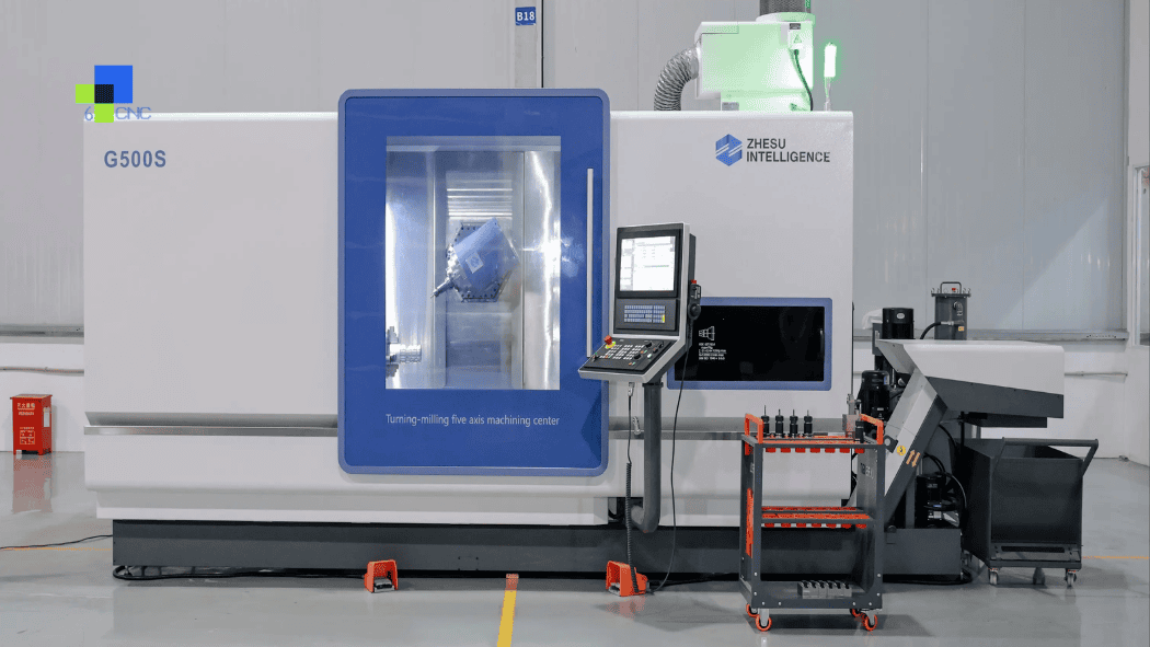
High-Speed Machining and 5-Axis CNC Milling
HSM and 5-axis machining are separate concepts, but they can work extremely well together.
5-axis machining allows the cutting tool to approach complex surfaces from different orientations.
HSM helps maintain efficient cutting conditions.
Potential advantages include:
- Shorter tools
- Better tool orientation
- Reduced setups
- Improved access
- More stable cutting
A shorter tool is particularly valuable because it reduces:
- Deflection
- Vibration
- Chatter
For complex small-batch parts, combining 5-axis positioning with optimized high-speed toolpaths can reduce both machining time and setup-related error.
Fast CNC Milling Is Not Always High-Speed Machining
The phrase fast CNC milling is often used commercially to mean:
- Short lead time
- Rapid machining
- Fast production
That is not necessarily the same as HSM.
A supplier may deliver a CNC part quickly because of:
- Machine availability
- Efficient programming
- Automated probing
- Good workflow
- Standardized tooling
even if the cutting strategy itself is conventional.
Conversely, a part may use HSM toolpaths but still have a longer total lead time because it requires:
- Heat treatment
- Grinding
- Inspection
- Surface finishing
Machining cycle time and manufacturing lead time should not be confused.
HSM vs. Conventional Milling
| Factor | Conventional Milling | High-Speed Machining |
|---|---|---|
| Spindle speed | Moderate | Typically higher |
| Feed rate | Moderate | Higher |
| Tool engagement | May vary considerably | Usually more controlled |
| Toolpath | Traditional | Smooth, optimized |
| Look-ahead demand | Lower | Higher |
| Acceleration demand | Lower | Higher |
| Chip generation rate | Moderate | Potentially very high |
| Machine dynamics | Important | Critical |
| CAM importance | High | Very high |
The boundary between the two is not absolute.
Modern CNC machining has adopted many HSM principles into everyday milling.
Sandvik notes that techniques once considered high-speed machining have increasingly become standard manufacturing practice.
HSM vs. High-Efficiency Milling
High-speed machining and high-efficiency milling are related but not identical.
HSM is a broad machining concept involving high cutting and feed speeds together with suitable machine dynamics and toolpaths.
High-efficiency milling, often abbreviated HEM, generally emphasizes:
- Low radial engagement
- Greater axial depth
- Consistent cutter engagement
- High feed
HEM-style toolpaths may therefore form part of a high-speed machining strategy.
But the terms should not automatically be treated as synonyms.
HSM vs. Trochoidal Milling
Trochoidal milling creates looping or curved tool motions designed to reduce cutter engagement in slots and pockets.
It is particularly useful when:
- Slot width is narrow
- Full-width engagement would overload the tool
- Stable engagement is desired
Trochoidal motion can form part of an HSM strategy.
Again, it is a toolpath method rather than the complete definition of high-speed machining.
High-Speed Machining Different Materials
HSM is not limited to aluminum.
But the strategy must change with the material.
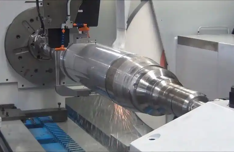
High-Speed Machining Steel
Steel requires lower cutting speeds than aluminum in many applications.
Tooling must account for:
- Higher cutting forces
- Greater heat
- Tool wear
Optimized dynamic toolpaths can still improve productivity by maintaining predictable cutter engagement.
High-Speed Machining Stainless Steel
Stainless steels require careful heat and chip control.
Depending on grade, they may exhibit:
- Work hardening
- High cutting forces
- Adhesive wear
A strategy that simply copies aluminum speeds and feeds would be inappropriate.
High-Speed Machining Titanium
Titanium presents a very different machining problem.
It has:
- Relatively low thermal conductivity
- High cutting temperatures
- Strong tool-wear tendencies
Modern constant-engagement toolpaths can still be valuable, but cutting speeds are dramatically different from aluminum machining.
This illustrates an important principle:
High-speed machining is material-specific.
Heat in High-Speed Machining
Machining converts energy into heat.
The heat is distributed among:
- Chips
- Cutting tool
- Workpiece
An effective machining strategy aims to keep excessive heat away from the finished component and cutting edge.
At high material-removal rates, good chip formation becomes especially important because chips are one of the primary ways heat leaves the cutting zone.
But heat behavior differs significantly between materials.
There is no universal statement such as:
Higher RPM always produces a cooler part.
The actual result depends on the entire cutting condition.
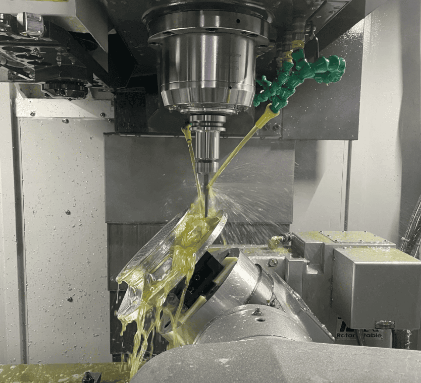
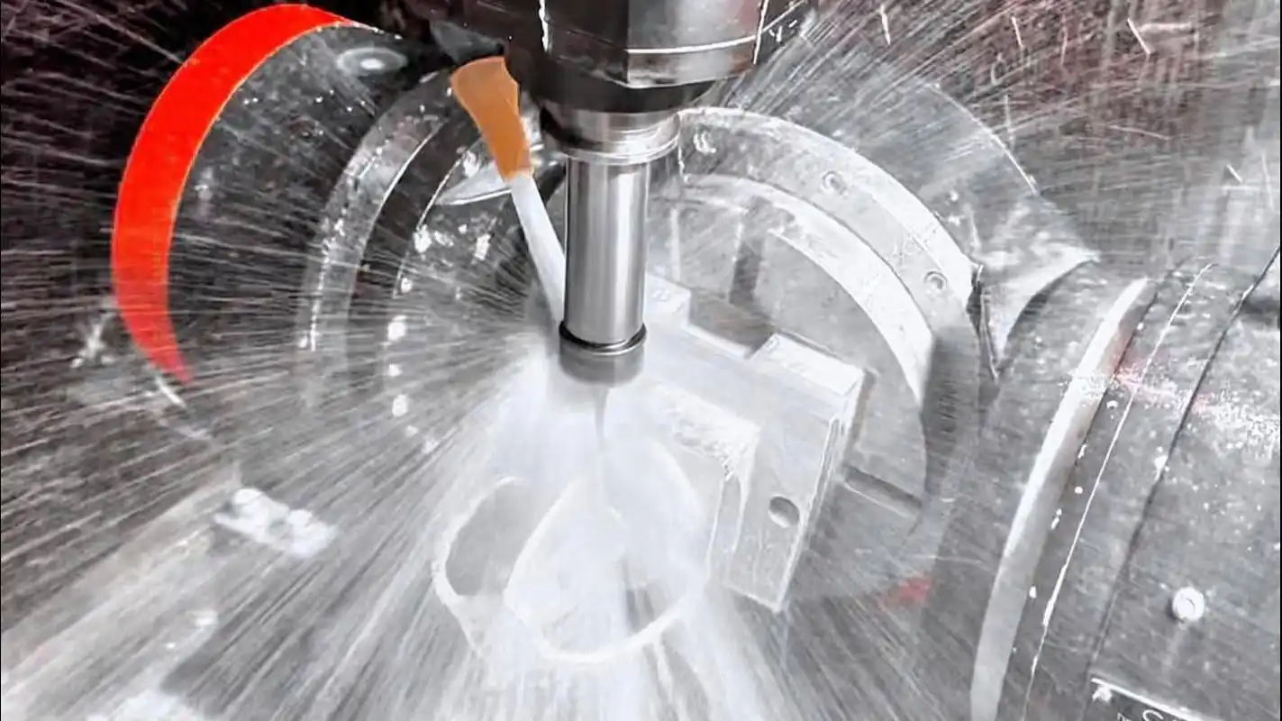
Coolant, Mist, and Air Blast
High-speed machining can use several chip-control and cooling strategies.
Depending on the material and application:
- Flood coolant
- Through-tool coolant
- Air blast
- Minimum quantity lubrication
- Mist systems
may be used.
For aluminum, the primary goals often include:
- Preventing chip recutting
- Reducing built-up edge
- Clearing deep pockets
- Maintaining tool condition
The most appropriate method depends on the machine, tooling, geometry, and material.
Built-Up Edge in Aluminum Machining
Aluminum can adhere to the cutting edge.
This is known as built-up edge.
Once material accumulates on the cutter, it can change the effective cutting geometry.
Potential effects include:
- Poor surface finish
- Dimensional change
- Increased cutting force
- Tool damage
Appropriate:
- Cutting geometry
- Tool coating
- Lubrication
- Chip load
- Cutting speed
help control this problem.
High-Speed Machining Deep Pockets
Deep pockets present several challenges.
The cutter becomes surrounded by material.
Chips must travel farther to escape.
Long tools may be required.
Potential problems include:
- Chip packing
- Tool deflection
- Vibration
- Recutting
- Poor surface finish
A good strategy may involve:
- Efficient roughing
- Controlled stepdowns
- Strong chip evacuation
- Shortest practical tooling
- Rest machining
- Separate finishing passes
Rest Machining
After a larger cutter roughs the component, material remains in areas the tool cannot reach.
Examples include:
- Small internal corners
- Narrow channels
- Complex transitions
Instead of using a small cutter to remachine the entire pocket, CAM can identify only the remaining material.
This is called rest machining.
It can significantly reduce unnecessary tool motion and improve small-tool reliability.
High-Speed Machining Internal Corners
Small internal corner radii often force the use of smaller tools.
Smaller cutters usually mean:
- Higher required RPM
- Lower rigidity
- Greater risk of deflection
This affects both cycle time and tool life.
When possible, designers should avoid making internal radii smaller than the functional requirement.
A slightly larger corner radius may allow:
- Larger cutter
- Shorter machining time
- Better tool stability
- Lower cost
This is an important DFM consideration for high-speed CNC parts.
High-Speed Machining and Surface Finish
A higher spindle speed can sometimes improve surface quality, but speed alone does not determine finish.
Surface quality also depends on:
- Tool runout
- Feed per tooth
- Tool geometry
- Machine vibration
- Toolpath smoothness
- Cutter condition
- Workpiece rigidity
An unstable cutter at 24,000 rpm can produce a worse surface than a stable cutter at 12,000 rpm.
Common Problems in High-Speed Machining
Chatter
Potential causes include:
- Excessive tool overhang
- Poor workholding
- Unstable spindle speed
- Incorrect radial engagement
- Toolpath resonance
Tool Breakage
Possible causes include:
- Chip recutting
- Excessive cutter engagement
- Poor runout
- Incorrect chip load
- Sharp toolpath changes
Aluminum Welding to the Tool
Potential causes include:
- Poor lubrication
- Incorrect cutter geometry
- Excessive rubbing
- Poor chip evacuation
Poor Dimensional Accuracy
Possible causes include:
- Tool deflection
- Workpiece movement
- Thermal effects
- Thin-wall distortion
- Excessive finishing load
Machine Cannot Reach Programmed Feed
This commonly occurs when:
- Toolpath segments are too short
- Acceleration is insufficient
- CNC processing is slow
- Sharp direction changes are frequent
The programmed feed rate is therefore not always the actual average cutting feed.
When High-Speed Machining Makes Sense
HSM is particularly useful when:
Large Amounts of Material Must Be Removed
For example, machining lightweight structures from aluminum billet.
The Material Supports High Cutting Speeds
Aluminum is the obvious example.
The Part Contains Complex Pockets
Smooth high-speed toolpaths can reduce engagement spikes.
Cycle Time Matters
Repeated small-batch or production orders benefit from optimized machining time.
Complex 3D Surfaces Are Required
High-speed contour control can improve productivity and surface continuity.
Multiple Similar Parts Will Be Produced
Programming and process optimization can be reused across the batch.
When HSM May Not Provide a Major Advantage
High-speed machining is not necessary for every component.
It may provide little benefit when:
- Only a small amount of material is removed
- Geometry is extremely simple
- Setup time dominates total production time
- Machine acceleration limits the toolpath
- Tooling cannot support the cutting conditions
- Workholding is weak
- The component is highly flexible
The fastest spindle setting is not automatically the lowest-cost process.
Design Considerations for HSM Parts
Use Practical Internal Radii
Avoid unnecessarily tiny pocket corners.
Consider Tool Access
Deep features may require long tools and reduce HSM stability.
Avoid Extremely Deep Narrow Slots
These create chip-evacuation and tooling problems.
Support Thin Walls
Consider the machining sequence when designing lightweight structures.
Separate Critical Finishing Requirements
Do not assume aggressive roughing should directly produce every final tolerance.
Roughing and finishing should serve different purposes.
High-Speed Machining and Tight Tolerances
High-speed machining can produce precision parts, but faster cutting does not automatically mean tighter tolerances.
Critical dimensions may require:
- Semi-finishing
- Tool measurement
- Compensation
- Controlled finishing passes
- Machine probing
- Temperature management
- Final inspection
For a precision part, a productive manufacturing strategy often separates:
High-speed material removal
from
controlled final finishing.
This provides both efficiency and dimensional reliability.
High-Speed Machining for Prototype Parts
Prototype CNC work often creates an interesting problem.
Quantity is low, but lead time matters.
The part may also change after testing.
HSM can be valuable because it allows complex parts to be created directly from billet without requiring dedicated tooling.
Typical examples include:
- Robotic components
- Aerospace prototype brackets
- Electronic housings
- Optical equipment structures
- Automation parts
But for a prototype, reducing cycle time by several minutes may matter less than:
- Efficient programming
- Quick setup
- Available material
- Inspection
- Fast revision handling
The complete manufacturing workflow should therefore be optimized rather than focusing solely on cutting speed.
HSM for Small-Batch Precision Production
High-speed machining becomes especially useful when a successful prototype moves into repeat orders.
Suppose a complex aluminum housing initially requires:
3 prototype parts
The process is developed and validated.
Later requirements become:
20 parts → 50 parts → 200 parts
At this stage, reducing machining cycle time while preserving the same dimensional strategy becomes increasingly valuable.
Optimized:
- Toolpaths
- Tooling
- fixtures
- probing routines
- cutting parameters
can be reused across subsequent batches.
This fits naturally into a Prototype → Small-Batch Production manufacturing model.
For 6CNC, small-batch custom precision machining does not mean making every part with the fastest possible cycle.
It means developing a machining process during the prototype or early batch stage that can remain accurate, repeatable, and economically sensible when the same component moves into small-batch production.
Speed vs. Process Reliability
A machining process that occasionally completes a part extremely quickly is not necessarily a good production process.
Small-batch manufacturing requires repeatability.
The better question is:
Can the same strategy machine part 1, part 20, and part 100 without unexpected tool failure or dimensional drift?
This requires balancing:
- Cycle time
- Tool life
- Surface finish
- Accuracy
- Chip evacuation
- Process stability
The best HSM parameters are therefore not necessarily the maximum values a machine can survive.
They are the values that produce the required part consistently.
High-Speed Machining and Automation
Once the cutting process becomes stable, additional productivity can come from areas outside the cut itself.
Examples include:
- Automatic probing
- Tool measurement
- Pallet systems
- Tool-life monitoring
- Fixture standardization
- Automated loading
For repeated small batches, reducing non-cutting time may sometimes produce greater savings than increasing spindle speed further.

How to Choose an HSM Machining Supplier
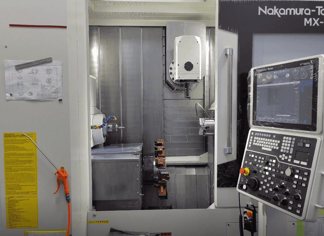
A supplier offering HSM machining services should understand more than maximum spindle RPM.
Useful capabilities include:
Suitable CNC Machines
The machines should provide appropriate:
- Spindle speed
- Feed capability
- Acceleration
- Rigidity
- CNC processing
Modern CAM Programming
High-speed machining depends heavily on efficient toolpaths.
Material-Specific Tooling
Aluminum, stainless steel, titanium, and tool steel require different machining strategies.
Workholding Experience
Especially for thin-wall and high-material-removal components.
Precision Inspection
Fast machining provides little value if the final part cannot be verified.
Process Planning
The manufacturer should know when to prioritize speed and when to slow down for critical features.
What Information Should You Provide for a High-Speed Machining Quote?
Provide:
- 3D CAD model
- 2D engineering drawing
- Material
- Quantity
- Dimensional tolerances
- Geometric tolerances
- Surface-finish requirements
- Critical features
- Required lead time
- Surface-treatment requirements
The CAD model is particularly useful because HSM process planning depends heavily on:
- Pocket depth
- Corner radius
- Wall thickness
- Tool accessibility
- Amount of material removal
A tolerance table alone cannot describe these machining conditions.
High-Speed CNC Machining for Custom Precision Parts
High-speed machining is not simply conventional CNC milling with a faster spindle.
An effective HSM process combines:
Machine Dynamics + CNC Control + CAM Toolpath + Tooling + Chip Load + Workholding + Material + Chip Evacuation
When these elements work together, manufacturers can achieve:
- Faster material removal
- Shorter machining cycles
- Stable tool engagement
- Efficient aluminum roughing
- Smooth 3D contouring
- Consistent small-batch production
Aluminum remains one of the strongest applications because its machinability allows high cutting speeds and high material-removal rates.
But HSM principles can also improve machining strategies for steels, stainless steels, titanium, and other engineering materials when cutting parameters are selected correctly.
At 6CNC, high-speed machining is part of the broader precision CNC machining process rather than a standalone promise about RPM.
For custom parts moving from prototype to small-batch production, the objective is to remove material efficiently during roughing, protect critical geometry during finishing, verify the required tolerances, and establish a process that remains repeatable across subsequent batches.
Send the complete CAD model and engineering drawing when evaluating a high-material-removal or complex CNC milling project. Part geometry will usually determine whether HSM provides a meaningful manufacturing advantage.
Frequently Asked Questions
What is high-speed machining?
High-speed machining is a CNC machining strategy that combines suitable high cutting speeds and feed rates with optimized tool engagement, smooth toolpaths, machine acceleration, and CNC control. It is not defined by one universal spindle-speed threshold.
Is high-speed machining the same as high RPM?
No. High RPM is only one element. Effective HSM also depends on feed rate, chip load, cutter engagement, machine acceleration, CAM toolpaths, CNC look-ahead, tooling, and chip evacuation.
What is high-speed milling?
High-speed milling applies HSM principles to milling operations. It typically uses higher cutting and feed speeds together with controlled cutter engagement and smooth CNC toolpaths.
Why is aluminum good for high-speed machining?
Aluminum has excellent machinability and can generally be cut at substantially higher speeds than many steels and high-temperature alloys. It is also frequently used in lightweight parts requiring large amounts of material removal.
Which aluminum grades are commonly used for high-speed CNC machining?
Common grades include 6061, 7075, and 2024. Cutting parameters should still be adjusted for the specific alloy, temper, geometry, and tool.
Does higher spindle speed always reduce machining time?
No. The machine must also maintain sufficient feed, acceleration, chip load, and toolpath efficiency. A high spindle speed with poor machine motion or low feed may provide little productivity improvement.
Why is chip evacuation important in high-speed aluminum machining?
HSM can generate large amounts of chips quickly. If chips remain in the pocket and are recut, they can increase heat, damage the tool, scratch the workpiece, and reduce process stability.
How many flutes are best for high-speed aluminum milling?
Two- and three-flute end mills are commonly used because they provide significant chip-clearance space. The best flute count depends on cutter diameter, radial engagement, operation, machine rigidity, and required material-removal rate.
What is constant tool engagement?
Constant or controlled tool engagement describes toolpaths designed to prevent large changes in the amount of cutter contacting the material. This helps stabilize cutting forces and allows higher, more consistent feeds.
Is HSM the same as adaptive milling?
No. Adaptive, dynamic, or similar constant-engagement toolpaths are techniques that can be used as part of an HSM strategy. High-speed machining is the broader manufacturing concept.
Is HSM the same as high-efficiency milling?
Not exactly. High-efficiency milling typically emphasizes low radial engagement, greater axial engagement, and consistent cutter load. It can form part of a broader high-speed machining strategy.
Can high-speed machining hold tight tolerances?
Yes, but high-speed roughing and precision finishing are often treated separately. Critical dimensions may require controlled finishing passes, tool compensation, probing, temperature management, and final inspection.
Is high-speed machining suitable for thin-wall parts?
Yes, but thin walls require careful machining sequences because cutting forces, residual stress, and clamping can cause deformation. High speed alone does not solve thin-wall machining problems.
Can HSM be used for steel?
Yes. High-speed machining principles can be applied to steels, although cutting speeds, tools, engagement, and cooling strategies differ significantly from aluminum.
Can HSM be used for titanium?
Optimized constant-engagement toolpaths can be useful for titanium, but machining parameters are very different from aluminum because titanium has more difficult thermal and tool-wear characteristics.
What parts benefit most from high-speed aluminum machining?
Typical applications include aerospace brackets, robotic components, electronic housings, structural frames, optical equipment components, automotive parts, prototypes, and other components requiring substantial material removal from aluminum billet.
Is high-speed machining useful for small batches?
Yes. It can reduce machining time for complex parts and becomes particularly useful when an initially validated prototype is repeated in quantities such as tens or hundreds of parts. The machining strategy can be optimized and reused across subsequent batches.
What information is needed for an HSM machining quote?
Provide the 3D CAD model, engineering drawing, material, quantity, tolerances, surface-finish requirements, critical features, and lead-time requirements. Part geometry is particularly important because pocket depth, wall thickness, internal radii, and material-removal volume strongly influence the HSM strategy.