A part can look clean in CAD and still create trouble on the machine. We see this often with first-pass designs that meet functional intent but ignore the realities of tooling access, workholding, tolerance stack-up, or inspection. That is where dfm for cnc machining matters. Good DFM does not water down your design. It helps you get the part you actually need, at the cost and lead time your project can support.
For product teams, DFM is not only an engineering exercise. It directly affects quote accuracy, scrap rate, delivery dates, and whether your supplier can hold the same quality from prototype to low-volume production. A feature that adds two extra setups or forces a custom tool may still be manufacturable. The real question is whether it is worth the added risk and cost.
What DFM for CNC machining really means
In practical terms, DFM for CNC machining is the process of adapting a part design to fit real machining constraints before production starts. We review geometry, tolerances, material, surface finish, hole strategy, and datum scheme. Then we ask a simple question: can this part be machined repeatably, inspected clearly, and delivered on time without unnecessary cost?
That last part matters. Many parts are technically machinable. Fewer are easy to machine consistently. A design that works for one prototype on a skilled programmer’s bench may become unstable when you need ten, fifty, or one hundred pieces with the same results.
This is why DFM should happen before the final PO, not after cutting begins. Early changes in CAD cost little. Late changes after setup, tooling, or partial production cost much more.
The biggest design decisions that change machining cost
Tolerances usually have the largest impact. If you apply tight tolerances across the full drawing, machining time rises fast. Inspection also becomes slower and more expensive. We often find that only a few critical interfaces truly need high precision, such as bearing fits, sealing faces, or alignment features. Other non-critical dimensions can be opened up without affecting function.
That distinction changes the quote. A tolerance of ±0.002 mm may be achievable on specific controlled features, but it should be assigned intentionally. If the whole part carries near-grinding-level expectations, your supplier may need slower feeds, more stable fixtures, in-process measurement, and additional finishing passes.
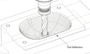
Feature depth is another common issue. Deep pockets, narrow slots, and small internal radii force the use of long-reach tools. Long tools deflect more. Deflection hurts surface finish, dimensional accuracy, and cycle time. If you increase an inside corner radius or reduce pocket depth, the same part often becomes much more stable to machine.
Wall thickness also deserves attention. Thin walls can vibrate, bend under clamp load, or move slightly as material is removed. Aluminum parts are especially prone to this if the geometry includes tall unsupported walls. In many cases, adding a little thickness or revising the machining sequence solves the problem with minimal effect on weight or function.
Why simple geometry usually wins
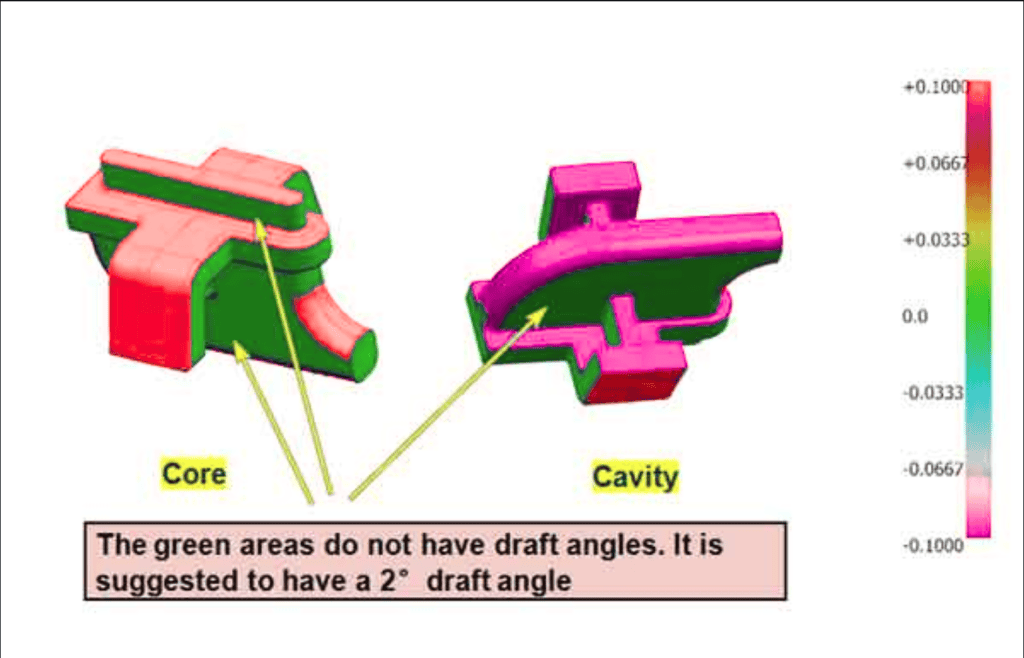
Complex geometry is not always bad. Five-axis machining makes many advanced forms possible. Still, geometry should earn its complexity. If a standard end mill can create a feature in one setup, that is usually a better production choice than a sculpted shape that requires specialized programming and extra repositioning.
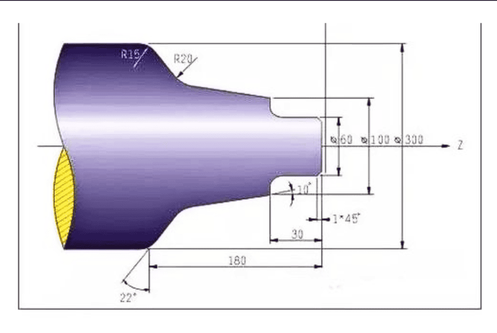
Internal corners are a classic example. CNC milling tools are round, so sharp internal corners are not natural. If your mating part does not absolutely require a square corner, adding a reasonable radius makes the feature easier to cut and inspect. If a square corner is functionally necessary, it may require EDM, a relieved corner, or a redesign of the assembly interface.
Threads can also be overdesigned. Very small threads in hard materials increase breakage risk. Excessive thread depth adds little practical strength beyond a certain point. For many metals, thread engagement around 1 to 1.5 times diameter is sufficient. More than that often adds machining time without meaningful benefit.
Material choice changes more than part strength
Engineers usually pick material based on strength, corrosion resistance, conductivity, or weight. Those are valid priorities. Machinability should still be part of the decision.
Take aluminum as an example. Grades like 6061 are widely used because they balance cost, machinability, and performance. Stainless steel offers corrosion resistance but usually takes longer to machine and can create more tool wear. Titanium can deliver excellent strength-to-weight performance, but cycle times and tooling costs rise quickly.
Plastics need the same scrutiny. POM, PTFE, PEEK, and acrylic all machine differently. Some hold tight tolerances well. Others move with heat or chip in thin sections. If your part has demanding flatness or cosmetic requirements, the right plastic grade can reduce risk before the first cut.
For buyers, this is where DFM becomes a commercial decision. A material change may cut machining time, reduce scrap, and shorten lead time without hurting product performance. It depends on the application, but the opportunity is often real.
DFM for CNC machining starts with setup count
Every additional setup introduces time and variation. The machine must locate the part again, the operator must verify alignment, and the process must maintain datum consistency across operations. More setups do not guarantee bad quality. They do create more opportunities for error.
When we review a drawing, one of the first things we check is how many orientations the part requires. If a feature can be moved to match an existing setup direction, production becomes simpler. If datums align with how the part will actually be fixtured and inspected, consistency improves.
This is especially important for low-volume production. At small batch sizes, setup time can dominate unit cost. A part that takes four setups instead of two may not look very different on the drawing, but the quote will reflect it.
Hole design is where many parts become expensive
Holes seem simple, yet they drive many avoidable problems. Very deep small-diameter holes are slower to drill and harder to evacuate chips from. Tight true position requirements across multiple hole patterns may require careful fixturing and probing. Cross-holes, interrupted holes, and angled entry conditions add complexity fast.
Standard drill sizes usually help. Standard thread sizes help too. Reamed holes, dowel holes, and precision fits should be reserved for locations where alignment or assembly performance truly depends on them.
We also recommend thinking about callout clarity. If a drawing mixes hole depths, thread depths, spotfaces, and tight positional tolerances without a clear datum strategy, programming and inspection both slow down. A cleaner drawing often improves lead time before machining even begins.
Surface finish and cosmetics need clear priorities
Not every surface needs the same finish. This sounds obvious, yet many drawings apply uniform finish requirements to the entire part. That can force unnecessary finishing operations on hidden or non-functional surfaces.
If a sealing face needs a fine finish, call out that face. If a cosmetic side must look clean after anodizing, state the appearance standard. If tool marks are acceptable inside a concealed cavity, that should be clear as well. Precision where it matters is good DFM. Precision everywhere becomes cost.
The same logic applies to edge treatment. A general break-edge note is often enough. Calling out unique edge conditions on every feature can create confusion unless those edges have a real safety or assembly function.
What good DFM feedback looks like from your supplier
Useful DFM feedback should be specific. It should point to exact features, explain the manufacturing consequence, and suggest realistic alternatives. General comments like make it simpler are not enough for an engineering team working against a release schedule.
A strong supplier will tell you things such as: this pocket requires a tool with excessive stick-out; this tolerance should be tied to a functional datum; this wall may move after roughing; this thread depth exceeds practical engagement; this material and finish combination may affect cosmetic yield.
That level of feedback reduces iteration. It also helps your purchasing team compare quotes more fairly. If one supplier is much cheaper, the reason may be better process planning. It may also mean they missed a risk hidden in the drawing.
At 6 CNC, we treat DFM as part of risk control, not just quoting. For precision parts, especially in prototype and low-volume programs, early manufacturability review often prevents the delays that matter most: redesign after inspection failure, last-minute tolerance disputes, and repeat builds caused by assumptions that were never validated.
When you should not optimize too aggressively
There is a limit to DFM simplification. Some features exist for real product reasons. A medical component, an automation fixture, or a high-speed assembly may need demanding geometry and tight positional control. The answer is not always to loosen the design.
The better approach is to separate must-have requirements from inherited drawing habits. If a feature drives product performance, keep it and build the process around it. If it came from an old revision, a conservative template, or a copied note, challenge it.
That is usually where the best savings appear. Not from making the part cheap, but from making the part intentional.
If you are sending out CNC parts for quoting, the most valuable question is not can this be machined. Ask how this part should be machined, where the real risks are, and which drawing decisions are driving cost without improving function. That conversation saves more time than any rushed revision later.

![Comparison of Operating Principles: This figure illustrates a microscopic comparison of the surface waviness and residual scallop height generated by a face milling cutter and a ball-nose cutter under different stepover and step-down settings. [Figure 4-1]](https://6-cnc.com/wp-content/uploads/2026/06/image-2-300x199.png)