Executive Summary: The Prototype Tolerance Matrix
- Dimensional Precision Thresholds: Standard precision milling safely delivers linear tolerances of ±0.05 mm to ±0.02 mm. Lathe turning inherently achieves superior diametrical control, holding ±0.01 mm under standard setups.
- The Deflection Variable: Tool and workpiece deflection are the primary drivers of dimensional non-conformance. Prototyping single pieces amplifies this risk due to the absence of iterative tool-wear compensation.
- Abrasive Finishing Indicators: Dimensional requirements tighter than ±0.005 mm or surface finishes smoother than Ra 0.4 μm typically dictate secondary cylindrical grinding or honing operations rather than pure subtractive cutting.
- The Single-Setup Tolerance Rule: Group high-precision features into a single coordinate layout. Re-fixturing intermediate prototype steps introduces part misalignment errors that consume the component’s tolerance budget.
1. The Physics of Tolerance Generation in Prototyping
In mass production runs, machinists tool up, measure scrap parts, and apply precision offsets within the CNC control unit to stabilize dimensional output. In low-volume prototyping, however, the machine operator must often hit dimensional targets on the very first or second piece. This constraints process margins significantly.
Achieving a specific tolerance band relies on managing the systematic variations of the machine tool, the mechanical properties of the material, and the kinematics of cutting forces.
During machining, the physical cutting force (Fc) exerts a uniform, counter-opposed pressure against both the tool tip and the raw stock. This mechanical stress causes structural components to flex. In prototyping, unexpected material stresses inside an un-annealed metal billet (like raw Aluminum 6061-T6 or Stainless Steel 304) can release during pocketing, distorting the part’s geometric shape after it is released from the machine jaws.
2. Achievable Machining Tolerances Table
To prevent cost escalation during design, engineering teams should reference standard commercial capability baselines before implementing tight tolerances. The following data details realistic limits for single-setup prototypes without requiring extensive custom staging:
| Feature Geometric Classification | Standard Precision Limit (Milling) | Ultra-Precision Threshold (Milling) | Standard Precision Limit (Turning) | Ultra-Precision Threshold (Turning) | Secondary Post-Processing Required |
|---|---|---|---|---|---|
| Linear Dimensions / Length | ±0.050 mm | ±0.015 mm | ±0.030 mm | ±0.010 mm | Surface Grinding (<±0.003 mm) |
| Shaft / Hole Diameters (OD/ID) | ±0.025 mm | ±0.012 mm | ±0.013 mm | ±0.005 mm | Cylindrical Grinding / Honing |
| Flatness / Coplanarity | 0.050 mm | 0.015 mm | 0.030 mm | 0.010 mm | Lapping / Double-Disk Grinding |
| Concentricity / Coaxial Runout | 0.030 mm | ±0.015 mm | 0.010 mm | 0.003 mm | Jig Grinding |
| True Position (Hole Patterns) | ±0.040 mm | ±0.015 mm | N/A | N/A | Coordinate Jig Boring |
Note: Achieving targets listed under the “Ultra-Precision” columns requires calibrated machine tools, temperature-controlled environments, and significantly reduced feed vectors, increasing piece-part run times.
3. Milling Tolerances: Flatness, Position, and Deflection Controls
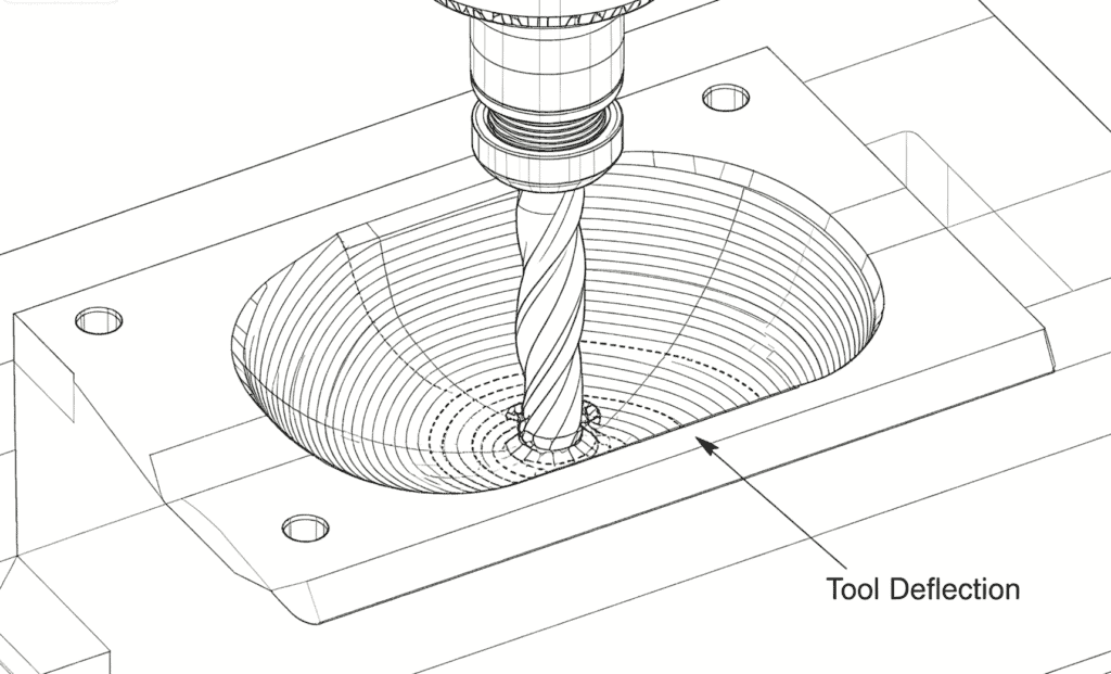
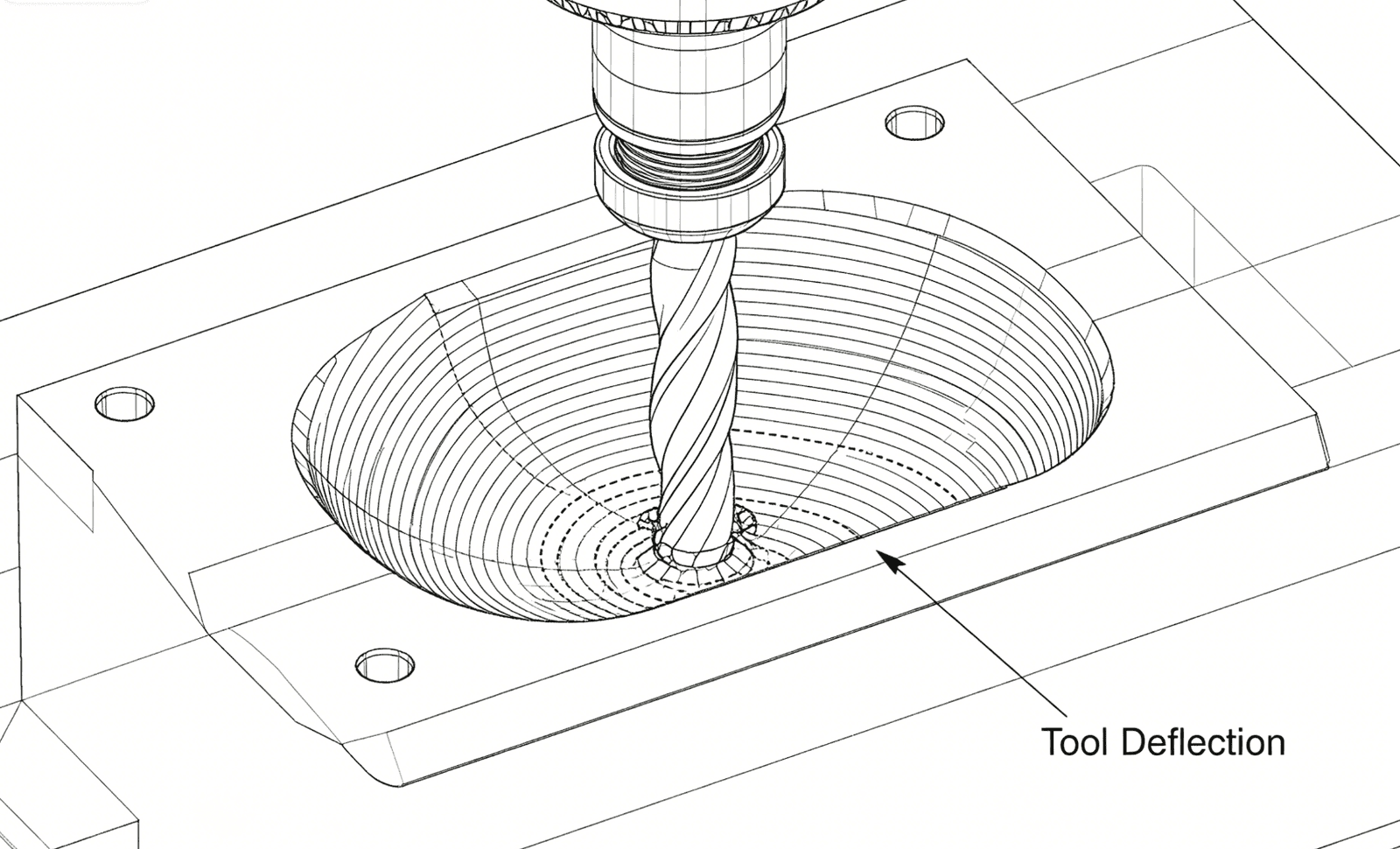
Tool Deflection Mechanics
When executing internal pocketing or profiling on a vertical machining center (VMC), the cutting tool acts as a cantilever beam held by the spindle toolholder. The radial cutting force causes the tool tip to deflect away from its nominal path.
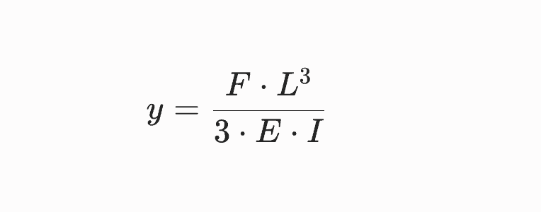
This mechanical deflection (y) is governed by the structural formula:
$$y = \frac{F \cdot L^3}{3 \cdot E \cdot I}$$
Where:
- L represents the extended tool reach length.
- E is the modulus of elasticity of the tool material (e.g., Tungsten Carbide).
- I is the area moment of inertia based on core diameter.
Because tool deflection increases with the cube of length (L3), a tool with a length-to-diameter ratio (L/D) exceeding 3:1 will experience severe deflection. This creates a tapered wall profile on the prototype rather than a true perpendicular surface, violating true position and perpendicularity tolerances.
Flatness and Positioning Variations
To secure flat profiles within 0.02 mm, designers must avoid interrupted geometries on thin structural planes. This prevents the raw stock from vibrating and lifting out of alignment during high-frequency face cuts on our precision CNC milling services.
4. Turning Tolerances: Diameters, Concentricity, and Structural Runout
Coaxial Precision Control
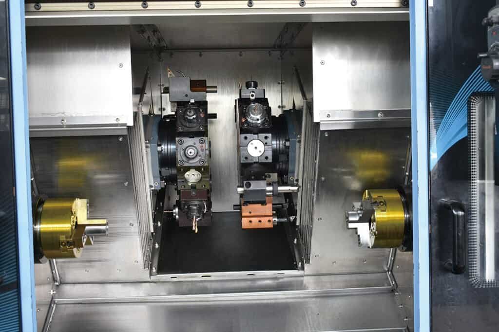
CNC turning centers hold tight diametrical tolerances due to the continuous nature of single-point shearing. When a cylinder is generated by a lathe tool, any axis of machine error is divided symmetrically across the center plane.
To maintain strict concentricity between adjacent shaft sections, engineers must design parts around the Single-Setup Principle. If Section A and Section B of a bearing journal are turned in one uninterrupted chucking cycle, the structural runout is dictated strictly by the accuracy of the main spindle bearings, which typically stays within ±0.002 mm based on the official ISO 2768-2 geometrical tolerance data sheet.
If the prototype design requires the operator to flip the shaft around and clamp the machined face in secondary chuck jaws to complete the back-side features, a re-fixturing error is introduced. Even with precision-ground soft jaws, this transfer introduces an automatic concentricity error of 0.015 mm to 0.03 mm, instantly consuming tight tolerance allowances.
5. When Subtractive Machining Fails: Indicators for Grinding and Honing
Subtractive cutting tool edges insert mechanical wedge forces into the material, leaving microscopic tearing marks on the surface finish. When design specifications exceed the structural limits of high-speed cutting inserts, engineers must route parts to abrasive finishing processes.
                  SURFACE FINISH & TOLERANCE THRESHOLDS
  +-----------------------------------------------------------------+
  | CNC Milling/Turning  | Ra 0.8µm - 3.2µm  | Limit: ±0.005mm      |
  +-----------------------------------------------------------------+
  | Abrasive Grinding    | Ra 0.2µm - 0.4µm  | Limit: ±0.002mm      |
  +-----------------------------------------------------------------+
  | Precision Honing     | Ra 0.1µm - 0.2µm  | Limit: ±0.001mm      |
  +-----------------------------------------------------------------+
Technical Indicators for Secondary Abrasive Finishing:
- Hardened Steel Alloys (>45 HRC): High-hardness parts (such as tool steel components or case-hardened shafts) generate elevated cutting forces that cause standard turning inserts to wear prematurely. The exact material yield point behavior under extreme cutting heat can be reviewed directly on the MatWeb Nitronic 50 High-Strength Property Sheet. These materials must be roughed out prior to heat treatment and then brought to final tolerance via cylindrical or surface grinding.
- Hydraulic and Pneumatic Sealing Interfaces: Dynamic piston rods and spool valves demand strict cylindrical roundness paired with surface finishes below Ra 0.4 μm to avoid seal degradation. Precision internal honing and grinding utilizes abrasive stones to flatten microscopic high points without modifying the axial centerline of the bore.
- Sub-Micron Dimensional Controls: If a component design specifies a shaft outer diameter with a total variation window of 0.004 mm (e.g., to match a high-speed ball bearing press-fit), standard turning methods face high risks of thermal contraction errors. Abrasive wheel finishing allows predictable micro-material removal rates, securing dimensional targets down to ±0.001 mm.
6. Manufacturing Cost and Setup Constraints
Designing parts with ultra-tight tolerances impacts prototype pricing. In multi-axis machining, reducing the tolerance window by half can triple the manufacturing cycle cost due to several key operational overheads:
- Extended Stabilization Cycles: To hold an ultra-precision diameter on an aerospace valve body, the machinist must add dedicated tool setting cycles, utilize precision test cuts on dummy blanks, and integrate extended warm-up sequences to counter spindle thermal expansion.
- Programming and Metrology Requirements: Verifying tight tolerances requires clean metrology handoffs. Operators must interrupt the machining process to deploy calibrated bore gauges or optoelectronic micrometers within the enclosure, adding setup delay hours.
- Abrasive Machine Pricing Premium: Routing a prototype part through a secondary ID/OD grinding or lapping workstation requires a dedicated operational setup, specific wheel dressing routines, and localized fixturing assets. This significantly increases component cost compared to drop-complete single-setup machining operations.
7. Quality Validation and the 6CNC Inspection Matrix
Translating micro-precision drawing specifications into verifiable prototypes demands robust, climate-controlled metrology platforms. The precision manufacturing environment at 6CNC pairs high-capability subtractive and abrasive equipment with advanced quality assurance verification systems:
- Subtractive and Abrasive Multi-Axis Matrix: Our facility operates high-speed 5-axis milling centers and sub-spindle live-tool turning lathes alongside precision surface and cylindrical grinding assets to deliver single-setup component validation.
- Metrology and Dimensional Inspection: All tight-tolerance prototypes undergo inspection using coordinate measuring machines (CMM) calibrated to the formal ISO 10360-2 CMM Verification Standards. This equipment allows us to verify true positions, cylindricity profiles, and complex geometric features down to a measurement resolution of 0.0015 mm.
- Surface Topography Verification: Microscopic finishes are evaluated using high-resolution profilometers to ensure total compliance with international ISO 21920 profile surface roughness definitions.
By integrating realistic DFM tolerances into your prototyping blueprints, you prevent unnecessary manufacturing cost expansion and accelerate production velocity. Upload your technical CAD models directly to the secure processing portal for an automated engineering DFM review and quote to lock in your project parameters.