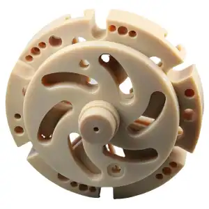
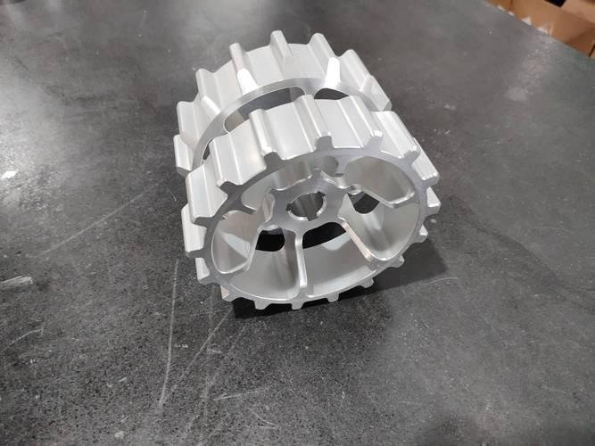
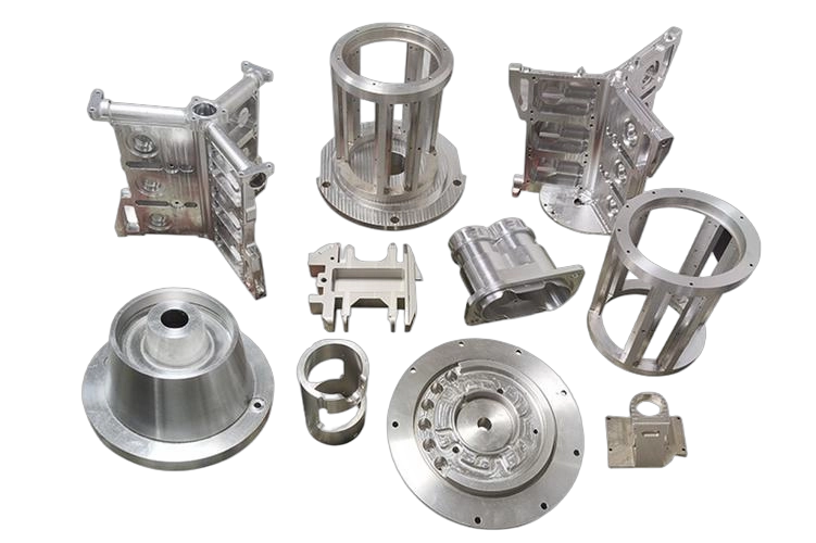
When developing precision hardware, Aluminium 6061-T6 is the gold standard for rapid prototyping and low-volume production. It offers an exceptional strength-to-weight ratio, excellent machinability, and responds beautifully to surface treatments. However, a frequent and costly failure point in hardware R&D occurs when an engineer measures a raw, newly machined prototype, confirms it is perfectly within specification, only to find it completely out of tolerance after it returns from the anodizing line.
Anodizing is not merely a cosmetic paint layer; it is an electrochemical conversion process that fundamentally alters the surface chemistry and physical dimensions of the substrate. In low-volume production—where statistical averaging cannot easily smooth out processing deviations—failing to calculate the dimensional shift caused by anodizing leads to ruined press-fits, binding bearings, and scraped assemblies.
This comprehensive guide breaks down the precise mathematical and metallurgical mechanics of post-anodizing tolerances, enabling design engineers to achieve perfect fitment straight out of the box.
1. The Chemistry & Mechanics of Dimensional Change
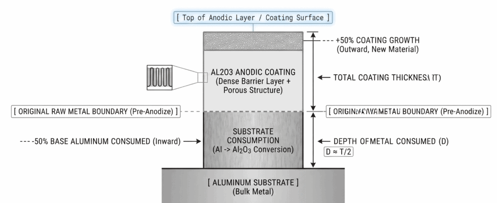
To accurately predict post-anodizing tolerances, we must look at the electrochemical interface of the anodic layer. Unlike plating (such as zinc or chrome coating), which sits entirely on top of the base metal, anodizing grows both inward into the material and outward from the original surface.
The 50/50 Penetration Rule
As a general engineering rule of thumb, the anodic oxide layer ($\text{Al}_2\text{O}_3$) builds up by consuming the base aluminum substrate. For every micron of total coating thickness ($T$), approximately $50\%$ penetrates below the original surface and $50\%$ grows outward.
$$\Delta D_{\text{surface}} = \frac{T}{2}$$
This means that for a single flat face, the dimensional increase equals half of the total anodizing coating thickness. However, when measuring a critical external diameter or thickness (where two opposing faces are treated), the total dimensional growth of the part matches the total coating thickness ($2 \times \frac{T}{2} = T$). Conversely, for an internal bore, the diameter will shrink by an amount equal to the total coating thickness.
Type II vs. Type III Anodizing Thickness Targets
According to data compiled by the National Institute of Standards and Technology (NIST), post-machining surface adjustments and finishing processes heavily dictate the final compliance of military and aerospace components. When dealing with defense-grade finishes under the MIL-A-8625 standard, the dimensional impact depends entirely on whether your drawing specifies Type II or Type III coatings:
- Type II Anodizing (Sulfuric Acid Anodizing): Typically yields a total coating thickness of $8\ \mu\text{m}$ to $25\ \mu\text{m}$ ($0.0003\text{“}$ to $0.0010\text{“}$). Following the 50/50 rule, a standard $10\ \mu\text{m}$ coating creates a linear dimensional increase of $5\ \mu\text{m}$ per surface ($+10\ \mu\text{m}$ on total external diameter).
- Type III Anodizing (Hardcoat Anodizing): Designed for extreme wear resistance and dielectric insulation. It yields a much thicker layer, ranging from $50\ \mu\text{m}$ to $75\ \mu\text{m}$ ($0.0020\text{“}$ to $0.0030\text{“}$). A typical $50\ \mu\text{m}$ hardcoat results in a massive $25\ \mu\text{m}$ growth per surface ($+50\ \mu\text{m}$ or $+0.002\text{“}$ on total external diameter), which can easily destroy a standard sliding or press fit if uncompensated in CAM.
2. Pre-Treatment Dynamics: The Impact of Bead Blasting
Engineers often overlook the fact that the post-anodizing dimension is highly dependent on the mechanical pre-treatment applied immediately before the parts enter the chemical tanks. For low-volume CNC 6061 prototypes, Bead Blasting is the most common method used to remove machining toolmarks and create a uniform, matte aesthetic.
Mechanical Erosion vs. Surface Peening
Bead blasting shoots microscopic media (typically glass beads, aluminum oxide, or ceramic shots) at high velocities against the raw aluminum surface. This process has a dual effect on tolerances:
- Material Erosion: Coarser media (such as #60 or #80 Aluminum Oxide) acts abrasively, stripping away raw metal. A heavy blast cycle can easily erode $5\ \mu\text{m}$ to $12\ \mu\text{m}$ of material from exposed faces.
- Surface Peening (Peak-to-Valley Levelling): Finer media (like Glass Beads #10 or #13) deforms the surface elastically, flattening the microscopic peaks left by the milling cutter into the valleys. While it removes minimal mass, it changes the measured micrometer dimension by altering the surface topology profile ($R_z$).
The Total Tolerance Chain
When combining bead blasting with anodizing, you are stacking two opposing dimensional variables. A typical preparation sequence changes dimensions as follows:
$$\text{Final Dimension} = \text{Raw Machined Dimension} – \text{Blasting Erosion} + \text{Anodizing Growth}$$
If an aggressive blast stage removes $8\ \mu\text{m}$ of diameter, and a subsequent Type II anodizing cycle adds $10\ \mu\text{m}$ of total diameter growth, the final part will only be $+2\ \mu\text{m}$ larger than the raw machined state. However, if the blasting step is skipped on a second batch, that batch will return at the full $+10\ \mu\text{m}$ size, introducing a $8\ \mu\text{m}$ batch-to-batch discrepancy. For low-volume orders where processing time is inconsistent, this variance can be catastrophic.
3. Process Capability ($C_p$ & $C_{pk}$) in Low-Volume CNC Prototyping
In mass production, high-volume automation allows shops to run statistical process control (SPC) to tighten tolerances. In low-volume prototyping (e.g., batches of 5 to 25 pieces), achieving a high process capability index ($C_p$ and $C_{pk}$) requires extreme discipline because there is no room for statistical averaging.
What Process Capability is Typical on $\pm0.001\text{ mm}$?
To put it bluntly: achieving a stable $C_{pk} \ge 1.33$ on a tolerance of $\pm0.001\text{ mm}$ ($1\ \mu\text{m}$) is practically impossible in standard commercial low-volume CNC machining—especially when post-processing is involved.
Under the statistical definitions outlined in ISO 22514 (Statistical methods in process management), process capability relies on tight control over a multi-variable system. To understand why sub-micron post-processing capability breaks down, let’s analyze the mathematical definition of the Upper Process Capability Index ($C_{pk}$):
$$C_{pk} = \frac{\text{USL} – \mu}{3\sigma}$$
Where $\text{USL}$ is the Upper Specification Limit, $\mu$ is the process mean, and $\sigma$ is the standard deviation.
If your tolerance window is $\pm0.001\text{ mm}$, the total allowable spread is just $2\ \mu\text{m}$. For a machine shop to hit a $C_{pk}$ of $1.33$, the entire process standard deviation ($\sigma$) must be kept under:
$$\sigma = \frac{0.001\text{ mm}}{3 \times 1.33} \approx 0.00025\ \mu\text{m}$$
A single $0.25\ \mu\text{m}$ variance can be triggered simply by a $1^\circ\text{C}$ temperature fluctuation in the workshop’s coolant tank, spindle thermal growth, or minor chemical variations across the anodizing rack. For a comprehensive look at how geometric errors are minimized prior to coating, see our advanced engineering guide on DFM for CNC: Deburring Reduction Without Manual Work.
Realistic Low-Volume Tolerance Expectations
For low-volume 6061 prototyping, engineers should align their designs with realistic, achievable process thresholds. The table below outlines achievable low-volume limits across various treatment stages:
| Feature Status | Critical Machining Tolerance | Achievable Cp (Low-Volume) | Achievable Cpk (Low-Volume) | Manufacturing Reality & Risk Assessment |
| Raw Machined (No Finish) | $\pm0.010\text{ mm}$ | $1.66$ | $1.45$ | Highly Stable: Easily maintained on high-end 3-axis and 5-axis machining centers with linear scales. |
| Bead Blasted + Type II Anodized | $\pm0.025\text{ mm}$ | $1.33$ | $1.10$ | Moderately Stable: Requires the machinist to deliberately under-size external features during CAM to absorb coating growth. |
| Bead Blasted + Type III Hardcoat | $\pm0.050\text{ mm}$ | $1.20$ | $0.95$ | Marginal: Thick coating variability means parts may require post-anodize sorting or automated matching. |
| Ultra-Precision Interfaces | $\pm0.002\text{ mm}$ | $<0.50$ | $<0.20$ | Unstable: Cannot be directly anodized to size. Requires specialized manufacturing sequences. |
4. Engineering Solutions: Sizing Critical Bores & Shafts
Given the compounding variables of tool wear, blasting erosion, and chemical coating growth, how do precision engineers successfully design high-accuracy interfaces like bearing bores and locating alignment pins on an anodized 6061 prototype?
The Manufacturing Sequence: Before vs. After Anodizing
There are two primary engineering approaches used to handle high-precision tolerances ($\pm0.005\text{ mm}$ or tighter) on parts that require an anodized finish:
Approach A: CAM Compensation (Pre-Sizing) — Best for Budgets
In this method, the drawing defines the final, post-anodizing dimension. The CAM programmer then mathematically back-calculates the coating growth and offsets the toolpath on the CNC machine accordingly.
- For a Bearing Bore (Final Target: $22.000\text{ mm} +0.010 / -0.000\text{ mm}$): Knowing that Type II anodizing will shrink the internal diameter by approximately $12\ \mu\text{m}$ ($6\ \mu\text{m}$ per side), the machinist programs the interpolating circular toolpath to bore the raw aluminum out to $22.012\text{ mm}$.
- The Caveat: This requires tightly coupled communication between the machine shop and the anodizing vendor. If the anodizer leaves the part in the acid tank slightly longer, the bore may over-etch or over-grow, throwing the prototype out of specification. To learn more about how cutting forces and paths affect raw edges before coating, read our analysis on Why CNC Machining Needs Post-Processing—And How to Reduce It.
Approach B: Post-Anodize Re-Machining / Masking — Best for Quality
For critical components where failure is not an option (such as aerospace housings or medical instruments), relying on chemical consistency is too risky. Engineers must deploy post-anodize isolation strategies:
- Liquid/Tape Masking: Prior to dipping the part in the anodizing line, a specialized chemical-resistant masking lacquer or rubber plug is inserted into the critical bore. This completely isolates the bore from the chemical reaction. The rest of the part receives its defensive oxide layer, while the critical bore remains raw, shiny, and perfectly true to its machined size.
- Post-Anodize Re-Machining (Post-Boring): The component is fully machined and anodized across all faces. Once returned from the finishing house, the part is re-fixtured on the CNC machine. A precision diamond-tipped boring bar sweeps the critical bore, cleanly shaving away the hard oxide layer and a fraction of the raw aluminum underneath to lock in a perfect, un-etched $\pm0.003\text{ mm}$ interface.
5. Strategic Capability Benchmarks: The 6CNC Baseline
In low-volume manufacturing, the key to eliminating assembly errors is data visibility. Precision manufacturing hubs like 6CNC provide a helpful baseline for understanding what standard advanced workshops can achieve without custom aerospace-grade cleanroom fees.
Across typical prototyping pipelines at 6CNC, standard production capability limits for Aluminium 6061-T6 are maintained at a baseline tolerance of $\pm0.015\text{ mm}$ for raw machined components. When shifting to post-treatment environments, a standard tolerance of $\pm0.025\text{ mm}$ is consistently supported for Type II anodizing through integrated pre-sizing algorithms within the CAM setup.
By utilizing these standard capability limits during your early-stage prototyping phase—and avoiding unachievable $\pm0.001\text{ mm}$ specifications on non-ground faces—design teams can secure maximum prototyping speeds, ensure reliable assembly fitment, and eliminate unexpected post-processing costs.
Conclusion
Controlling post-anodizing tolerances on low-volume CNC 6061 prototypes is a balancing act between material science and mechanical precision. By applying the 50/50 penetration rule, accounting for the erosive effects of bead blasting, and recognizing that sub-micron tolerances cannot survive chemical baths without strategic masking or post-boring, engineers can bridge the gap between digital CAD designs and flawless physical components.