Slots appear in brackets, machine frames, adjustment plates, keyways and enclosure components. Their function may be simple, but the machining load is not. A cutter engaged on both sides has less room to release chips and more opportunity to deflect.
Reliable slot milling starts by matching the toolpath to the slot type, depth, width tolerance and end condition. This guide shows what changes when a slot is open, closed, deep, narrow or required to locate another component.
Classify the slot before choosing a tool
An open-ended slot allows the cutter to enter from outside the material. A closed slot requires plunging, helical entry or a predrilled entry point. T-slots and undercut slots require a second tool after the access channel is created. Keyways may place stronger demands on width, position and floor geometry.
The end shape matters too. A standard end mill leaves a semicircular end based on its diameter. A square closed end or special relief may require a different path or secondary process.
Why full-width cutting needs control
When the cutter diameter matches the slot width, both sides of the tool remain engaged. Cutting force and chip thickness vary as each flute enters and exits. Chips can be trapped in the path and recut, raising heat and degrading the wall finish.
For a precision slot, a smaller roughing tool can leave material on both walls. Separate finishing passes then bring each wall to dimension. This gives the process more control over width and allows compensation for tool wear.
The method may take more tool motion, but it is often faster overall than correcting an undersized, tapered or damaged slot.
Width, depth and corner decisions
Deep narrow slots require slender tools and careful evacuation. Increasing the slot width may permit a stiffer tool. If only the upper portion controls assembly, consider whether the full depth needs the same width tolerance and finish.
Internal bottom corners follow the cutter geometry. State whether the floor-to-wall radius is functional. A small radius across the full depth can drive special tooling without improving performance.
For slots used as adjustment features, clarify whether the width, centerline position or end-to-end travel is the critical requirement. Those are different inspection tasks.
Inspection and burr control
Slot width can be checked with pins, gauge blocks, calipers, a CMM or optical equipment depending on size and tolerance. The measurement method should capture taper if both upper and lower widths matter.
Burrs often form at slot exits and intersecting holes. Specify the acceptable edge condition and protect functional corners from uncontrolled hand deburring. For keyways and locating slots, excessive edge rounding can affect fit even when the measured width remains acceptable.
Slot milling process selection
| Slot type | Typical approach | Main risk |
|---|---|---|
| Open slot | Enter from an outside edge | Exit burr and wall deflection |
| Closed slot | Helical or ramp entry | Chip packing and entry marks |
| Precision-width slot | Rough, then finish each wall | Tool wear and taper |
| Deep narrow slot | Staged depth with controlled evacuation | Chatter and tool breakage |
| T-slot | Create access slot, then use T-slot cutter | Neck strength and trapped chips |
| Keyway | Control width, centerline and edge condition | Fit and alignment error |
Full slotting is a 100% radial-engagement cut
When cutter diameter equals slot width, radial width of cut ae equals 100% of cutter diameter. The tool cuts on both sides, chip space is restricted and radial forces can alternate as flutes enter each wall. This is a different loading condition from side milling at a small radial engagement.
Toolmaker guidance therefore favors chip space and stable, short assemblies for full slotting. Sandvik identifies coarse-pitch cutters as a first choice for full-slot operations and difficult conditions because fewer engaged edges leave larger chip pockets. The best flute count still depends on tool diameter, material and machine capability.
Use feed-per-tooth and engagement together
Linear table feed follows Vf = n × z × fz. Increasing flute count z increases programmed feed at the same chip load, but only if chips can evacuate and spindle power can support the engaged edges. Packing more flutes into a closed deep slot can reduce the space available for chips.
Material removal rate can be approximated as Q = ap × ae × Vf. In a full-width slot, ae is fixed by cutter diameter, so axial depth ap and feed Vf must stay within the stable power, chip and deflection window. Splitting depth into several levels may produce a higher reliable throughput than one deep pass that causes chatter or breakage.
Worked example: a 10 H7 locating slot
Suppose a 10 mm nominal slot locates a sliding component and must control width more closely than the surrounding profile. Cutting it once with a nominal 10 mm end mill gives little control over tool runout, wear, deflection and actual cutter diameter. The slot may cut oversize, while compensation cannot independently correct both walls.
A controlled approach roughs with a smaller tool, leaves stock on both walls and finishes them separately. The process can measure the first piece and adjust radial compensation. The drawing should specify whether the slot center plane, width or both control assembly. If position is critical, the slot should reference the same datums used by the mating features.
Entry strategy changes tool load
An open slot permits entry from outside the workpiece and gives chips a clear escape path. A closed slot needs a ramp, helix, predrilled entry or a tool designed to plunge. Straight plunging loads the center of an end mill, where cutting speed approaches zero; not every end mill is center cutting.
For deep closed slots, a predrilled entry can remove the highest-risk center material. Helical entry spreads the load around the cutter. The programmed ramp angle must match the toolmaker’s guidance; copying a value from a different diameter or material is not reliable.
Climb and conventional cutting affect opposite walls
In a full-width slot, one side of the cutter operates in a climb relationship while the opposite side operates conventionally. Tool deflection can therefore shift the slot and produce different finishes on each wall. Finishing the two walls in separate passes lets the programmer choose a consistent cutting direction and controlled engagement for each.
Burr location helps diagnose the process
Burrs tend to form where the cutting edge exits unsupported material. Slot ends, thin floors and intersections with cross-holes are common sites. A burr can indicate tool wear, an unfavorable exit direction, insufficient edge support or a material-specific ductility problem.
The drawing should define whether edges may be chamfered, radiused or only lightly broken. A generic deburr note can damage a sharp locating edge or change the effective width of a shallow keyway.
Technical references
- Sandvik Coromant Milling Tools catalogue: cutter pitch and full slotting
- Sandvik Coromant side-and-face milling setup
- Autodesk Fusion 2D Pocket entry and finishing reference
What to send with your RFQ
- Open or closed entry condition
- Slot width, depth and end geometry
- Functional tolerance: width, position or both
- Required floor and wall finish
- Intersection with holes or other slots
- Permitted corner radius and edge break
- Inspection and gauge requirements
A useful RFQ gives the manufacturing team enough information to separate functional requirements from preferences. If a feature is difficult to reach or inspect, a short engineering review before release can prevent a costly revision later.
Review the part before production
Send 6CNC your CAD model, drawing, material and quantity. Our team will review machining access, setups, critical tolerances and inspection needs before quoting.
Frequently asked questions
What is the difference between slot milling and side milling?
Slot milling forms a channel with engagement on both sides, while side milling primarily cuts one side surface or edge.
Should the cutter diameter equal the final slot width?
It can for non-critical work, but precision slots often benefit from a smaller roughing tool followed by separate wall-finishing passes.
How are closed slots entered?
Common methods include ramping, helical interpolation and entry through a predrilled hole, depending on the tool and geometry.
Why is a machined slot tapered?
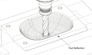
Tool deflection, workpiece movement, wear and long reach can make the slot width vary with depth.
Plan the process around the functional features
Good CNC machining starts with a clear definition of what the part must do. Tool access, rigidity, datums and inspection should support that function. For additional process options, see our CNC milling services, 5-axis machining and quality assurance resources.

![Comparison of Operating Principles: This figure illustrates a microscopic comparison of the surface waviness and residual scallop height generated by a face milling cutter and a ball-nose cutter under different stepover and step-down settings. [Figure 4-1]](https://6-cnc.com/wp-content/uploads/2026/06/image-2-300x199.png)