A perfectly sharp internal corner is easy to draw and impossible to produce with a standard rotating end mill. The cutter has a radius, so the machined corner inherits one. Asking for a smaller corner means using a smaller and often less rigid tool.
That tool choice affects more than appearance. It changes reach, feed rate, tool life, wall finish and the number of operations. A better radius decision can shorten machining time while making the part more consistent.
Why an internal radius remains
An end mill removes material with a circular cutting edge. When it follows two intersecting walls, the tool center cannot enter the theoretical sharp corner. The remaining material forms an arc equal to the cutter radius unless another process removes it.
External corners are different because the tool can travel around the outside profile. Confusing internal and external requirements often leads to unnecessary notes on drawings.
Radius, cutter diameter and pocket depth
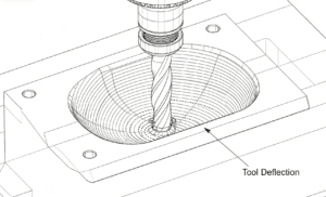
A small radius requires a small cutter. If the pocket is deep, that cutter must also be long enough to reach the floor. Small diameter plus long reach is a low-rigidity combination, increasing chatter and deflection risk.
Specifying a corner exactly equal to the tool radius can also be inefficient. The cutter becomes heavily engaged as it enters the corner and must change direction under load. Providing a slightly larger part radius lets the tool interpolate the corner with smoother engagement.
The correct value depends on depth, material, wall tolerance and available tooling. Treat radius and depth as one design decision, not separate dimensions.
When the mating part has a square corner
A rectangular insert or cover may appear to require a sharp pocket. Often it only requires clearance. Dog-bone or T-bone reliefs remove material beyond the theoretical corner so the mating part can seat without making the entire corner small.
Another option is to chamfer the mating part, add a matching radius or use a separate component. These choices should be evaluated against sealing, stress and appearance rather than selected only for machining convenience.
Alternatives when sharp corners are functional
Wire EDM can produce very small internal radii in through-features. Sinker EDM may address blind geometry. Broaching can create repeated internal forms in suitable production parts. Each adds tooling, setup or lead-time considerations.
Before adding a secondary process, confirm the exact region that needs relief. A short local sharp feature costs less to solve than applying the requirement along the full pocket depth.
Internal corner design choices
| Requirement | Preferred approach | Tradeoff |
|---|---|---|
| General pocket | Use a generous standard radius | Lowest machining risk |
| Deep pocket | Increase radius with depth | May require mating-part change |
| Square insert clearance | Use dog-bone or mating chamfer | Relief remains visible |
| Local sharp corner | Limit secondary processing to the local area | Additional operation |
| Sharp through-profile | Evaluate wire EDM | Higher process cost |
| Repeated production form | Evaluate broaching or special tooling | Upfront tooling cost |
The cutter-to-corner relationship is more important than fit alone
A cutter with radius Rt can enter a modeled internal corner of radius Rp only when Rt ≤ Rp. Geometric fit is the minimum condition, not a good process condition. When Rt approaches Rp, the cutter engagement angle rises sharply in the corner. Cutting force and deflection rise at the same time the tool must reverse direction.
Autodesk gives a practical rule of thumb: choose a tool radius around 80% of the minimum concave part radius. Under that rule, an R5 pocket corner is better approached with about an R4 tool radius, corresponding to an 8 mm cutter, rather than a 10 mm cutter that exactly matches the corner. It is guidance, not a universal tolerance rule, but it creates room for the toolpath to blend the turn.
Worked comparison: R5 and R6 corners
Consider a 30 mm-deep aluminum pocket. With an R5 specified corner, a 10 mm tool geometrically fits but becomes fully engaged in the turn. Choosing an 8 mm cutter leaves 1 mm radial difference between the tool and part radii, allowing CAM to generate a smoother path.
If the design moves to R6, the 10 mm tool radius becomes about 83% of the part radius. The tool has a 2.44 times larger d⁴ stiffness term than an 8 mm cutter before flute geometry is considered. The larger core and smoother engagement can improve both wall accuracy and tool life.
Corner radius also controls rest machining volume
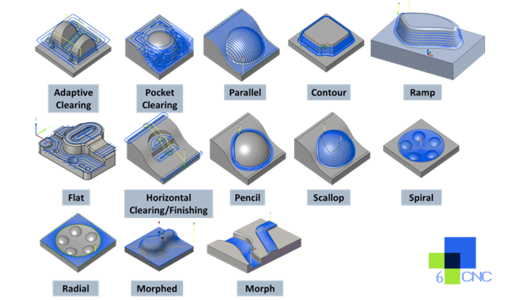
A large roughing tool removes bulk material efficiently but leaves cusps in smaller internal corners. CAM rest machining calculates the material the previous tool could not reach and directs a smaller tool only to those regions. The programmer must enter the prior tool diameter and its physical corner radius correctly; Autodesk distinguishes that tool corner-radius field from the radius modeled on the part.
Designers can reduce this secondary workload by using consistent functional radii. Five different small radii may force several tools or conservative selection based on the smallest one. Standardizing non-critical corners around one available tool family reduces programming, tool changes and inspection variation.
Vertical corner radius and floor fillet are different controls
The plan-view radius between two vertical walls is primarily linked to cutter diameter. The floor-to-wall fillet is linked to end-mill corner geometry, such as a square, corner-radius or ball-nose tool. A drawing that calls both simply “R2 all around” may unintentionally require a ball or bull-nose tool along the floor.
State the vertical corner radius and floor fillet separately. If the floor fillet is not functional, allow the manufacturer to use the standard edge preparation of the selected cutter. If it is a stress-control feature, define it and the blend zone deliberately.
Dog-bone relief: calculate what must clear
A dog-bone relief is not automatically acceptable because it changes the outer envelope of the pocket. Locate the relief where it does not break a sealing land, reduce thread wall thickness or create an unwanted stress riser. Its diameter must clear the mating part corner after considering part tolerances and assembly misalignment.
For a rectangular insert with a sharp nominal corner, the designer can also chamfer the insert. This often keeps the pocket exterior cleaner and may be easier if the insert already receives an edge break. Compare which component is easier to modify and inspect.
Inspection must match the corner function
A radius gauge can screen an accessible corner but does not verify its location, tangency or full depth. Optical measurement or CMM scanning may be needed for a functional profile. If the real requirement is simply assembly clearance, a functional gauge or mating-part check can be more meaningful than a tight radius tolerance.
Technical references
- Autodesk: machining internal corners
- Autodesk Fusion 2D Pocket reference
- Autodesk Rest Machining corner-radius clarification
What to send with your RFQ
- Identify which corners are functionally constrained
- Show pocket depth beside the radius requirement
- Check whether the mating part can be chamfered
- Allow corner relief where appearance permits
- Avoid applying one tiny radius to every internal edge
- Mark any region that requires a secondary process
A useful RFQ gives the manufacturing team enough information to separate functional requirements from preferences. If a feature is difficult to reach or inspect, a short engineering review before release can prevent a costly revision later.
Review the part before production
Send 6CNC your CAD model, drawing, material and quantity. Our team will review machining access, setups, critical tolerances and inspection needs before quoting.
Frequently asked questions
Can a CNC mill make a zero-radius internal corner?
No. A rotating milling cutter leaves a radius. A secondary method such as EDM or a designed relief is required for a functionally sharp corner.
Why not use the smallest available end mill?
A smaller tool is less rigid, especially at long reach. It may increase cycle time, chatter, breakage risk and dimensional variation.
What is a dog-bone corner?
It is a relief that extends beyond a pocket corner so a square mating part can fit despite the end mill radius.
Should all internal corners use the same radius?
Consistent radii can reduce tool changes, but only when the chosen value works with depth and function. Critical local corners can be specified separately.
Plan the process around the functional features
Good CNC machining starts with a clear definition of what the part must do. Tool access, rigidity, datums and inspection should support that function. For additional process options, see our CNC milling services, 5-axis machining and quality assurance resources.

![Comparison of Operating Principles: This figure illustrates a microscopic comparison of the surface waviness and residual scallop height generated by a face milling cutter and a ball-nose cutter under different stepover and step-down settings. [Figure 4-1]](https://6-cnc.com/wp-content/uploads/2026/06/image-2-300x199.png)