CNC machines can deliver impressive accuracy. But good results rarely come from the machine alone.
A modern machining center may have excellent positioning accuracy, rigid construction, high spindle speeds, and advanced controls. Even so, the finished part can still suffer from dimensional drift, poor surface finish, deformation, chatter, rapid tool wear, or inconsistent quality from one piece to the next.
The real difference usually lies in the process surrounding the machine—tool selection, workholding, datum strategy, machining sequence, cutting parameters, inspection, and how much material you leave for finishing.
Whether you are machining prototypes, custom parts, or repeat small batches, the following ten tips can help improve accuracy, reduce unnecessary machining time, and make the process more predictable.
1. Start with the Functional Requirements, Not Just the CAD Model
One of the most important CNC decisions happens before anyone opens the CAM software.
A CAD model shows geometry. It does not always show which features actually matter.
Consider a typical housing. It might contain two bearing bores, four mounting holes, several threaded holes, an outer profile, a cosmetic surface, and a locating face. All of these features appear in the same model, yet they are not equally important. The bearing bores may need tight dimensional and positional control, while several exterior dimensions can tolerate much larger variation.
Treating every feature as equally critical increases cost without improving performance.
Identify critical-to-function dimensions
Before machining begins, review:
- Tight dimensional tolerances and GD&T requirements
- Mating surfaces, sealing surfaces, and bearing locations
- Alignment features, press fits, and sliding fits
- Optical or measurement surfaces
These features should drive the machining strategy. They often need dedicated finishing operations, controlled tool offsets, in-process inspection, CMM verification, or more stable workholding.
This mindset is especially valuable in precision small-batch production, where the goal is not simply to make one acceptable part, but to keep critical features consistent across the entire batch.
2. Choose Datums and Workholding Before Building the Toolpath
Poor workholding decisions create problems that even the best CAM software cannot fix.
A part needs a stable physical reference before any dimensional relationship can be controlled reliably. The machining datum should therefore be chosen based on both the engineering drawing and the actual manufacturing sequence.
A good datum strategy should:
- Provide repeatable positioning
- Support important geometric relationships
- Minimize unnecessary re-clamping
- Remain accessible throughout machining
- Resist cutting forces without distorting the workpiece
Whenever practical, machine important features from the same datum structure. Suppose a housing has two precision bores whose center distance is critical. Machining both bores in one setup usually reduces positional error compared with machining one bore, removing the part, rotating it, and then machining the second.
That second approach is not automatically wrong—but the fixture and datum transfer now become part of the tolerance chain.
Avoid unnecessary setups
Every setup can introduce locating error, clamping variation, operator variation, and datum-transfer error. For complex geometry, 4-axis or 5-axis machining can sometimes eliminate several separate setups.
The goal is not to minimize setups at any cost. The goal is to minimize setups while still maintaining rigidity, accessibility, and process stability.
3. Separate Roughing and Finishing When Accuracy Matters
Roughing and finishing serve different purposes.
Roughing removes material efficiently. Finishing establishes final geometry, tolerance, and surface condition. Trying to do both with one strategy often creates unnecessary variation.
Heavy material removal brings higher cutting forces, more heat, greater vibration, changing internal stress, and larger tool loads. The workpiece can shift slightly after roughing—especially with thin-wall parts, long parts, aluminum plate, large housings, asymmetric components, or stress-sensitive material.
A more stable approach
For precision work, consider this sequence:
- Rough the major geometry first
- Leave controlled stock on critical surfaces
- Allow the part to stabilize if needed
- Re-establish critical references
- Finish the important dimensions under lighter, more stable conditions
How much finish stock to leave depends on material, geometry, tolerance, cutting method, and part rigidity. Too much increases finishing forces. Too little may not remove the deformation, roughing marks, or dimensional variation from the earlier operation.
The principle is simple: do not ask the roughing operation to create the final precision condition.
4. Use the Shortest and Most Rigid Cutting Tool That Can Reach the Feature
Tool rigidity has a major effect on machining performance.
Long overhang behaves like a lever. As the cutting edge moves farther from the holder, the tool becomes more susceptible to deflection and vibration. The results can include chatter, dimensional error, tapered walls, poor surface finish, accelerated wear, or sudden tool failure.
This becomes especially critical when machining deep pockets or cavities.
Avoid automatically choosing a long-reach tool
A better approach is often to use several tools of increasing length:
- A short end mill for upper features
- A medium-length tool for intermediate areas
- A long-reach tool only where its extra reach is actually required
Most material is then removed with the more rigid tool. The long-reach cutter is used only in the areas that truly need it.
Five-axis machining can help
Five-axis positioning can tilt the component or the tool to improve access. That often allows a shorter tool than would be required on a 3-axis machine. In these cases, five-axis machining improves not only geometric access but also cutting stability.
5. Do Not Choose Cutting Parameters from Material Alone
It is tempting to look up a recommended cutting speed for a material and use that value throughout the program. Real CNC machining is more nuanced.
Cutting conditions should reflect the full system: workpiece material, cutter diameter, tool material and coating, number of flutes, radial and axial engagement, tool overhang, machine rigidity, workpiece rigidity, and coolant strategy.
Two operations may both machine 7075 aluminum yet require very different parameters. A rigid end mill making a shallow finishing pass is not operating under the same conditions as a long-reach tool cutting a deep pocket. Titanium, of course, demands an entirely different approach from aluminum.
Watch the real process
Signs that parameters need adjustment include unstable cutting sound, excessive vibration, unusual chip shape, rapid edge wear, built-up edge, excessive heat, or inconsistent surface finish.
Treat recommended cutting data as a starting point, not an absolute rule. Stable production parameters are developed by combining published data with the actual behavior of the machine, tooling, fixture, and part.
6. Design Toolpaths Around Cutting Forces, Not Just Cycle Time
The shortest toolpath is not always the best toolpath.
CAM systems can generate extremely efficient motion, but machining stability must remain the priority. Sudden changes in tool engagement create abrupt changes in cutting force. That can lead to chatter, cutter deflection, inconsistent surface finish, or tool damage.
Maintain more consistent engagement
Modern roughing strategies often use controlled radial engagement to keep cutting loads more predictable. This is especially useful for deep pockets, hard materials, long-reach tools, and high material-removal rates.
Entry and exit moves matter as well. Direct plunging is not always the best option. Depending on the cutter and geometry, ramp entry, helical entry, pre-drilled entry, or open-side entry may be more appropriate.
Finishing toolpaths need the same care. The direction of the finishing pass can affect surface quality, particularly on freeform surfaces and complex contours.
Toolpath decisions should therefore balance accuracy, tool life, surface finish, machining stability, and productivity—not just the shortest possible machine movement.
7. Control Heat Before It Becomes a Dimensional Problem
CNC machining generates heat. Some leaves with the chip, some enters the tool, some remains in the workpiece, and some enters the spindle and machine structure.
For loose-tolerance parts, small thermal changes may have little practical effect. For precision work, thermal variation can become part of the tolerance problem itself.
A simple example
A long metal component measured immediately after heavy machining—while still warm—will not necessarily show the same dimensions after it returns to stable room temperature. The machine itself also changes temperature during the day. A center that has just started in the morning can behave slightly differently after several hours of continuous production.
Thermal control can include:
- Consistent machine warm-up routines
- Stable coolant conditions
- Appropriate cutting parameters that avoid unnecessary heat buildup
- Controlled inspection temperature
- Allowing precision parts to stabilize before final measurement
This becomes increasingly important as tolerances tighten or part size increases. Thermal control does not always require sophisticated climate systems. Often it begins with simply recognizing that temperature is another manufacturing variable.
8. Pay Attention to Workpiece Rigidity as Material Is Removed
A workpiece does not stay equally rigid throughout the machining cycle.
A solid block at the start can become a flexible structure near the end. This is common with thin-wall housings, frames, brackets, aerospace structures, enclosures, and lightweight robotic components.
Machining sequence therefore affects the mechanical behavior of the part.
Preserve support for as long as possible
When practical, keep rigid material around sensitive features until major cutting operations are complete. Temporary structures—tabs, ribs, sacrificial material, temporary walls, or custom fixture supports—can provide stability during machining and be removed later.
Machining extremely thin areas early leaves the part vulnerable to vibration or deformation in later operations. A good sequence asks not only which feature should be produced next, but also how each material-removal step changes the rigidity of what remains.
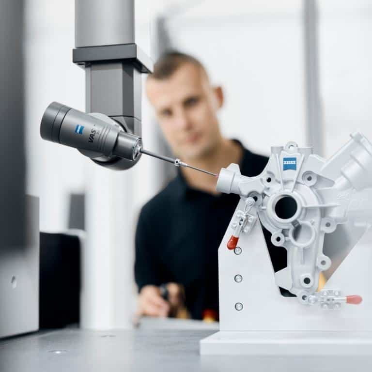
9. Inspect During Machining, Not Only After the Part Is Finished
Final inspection is necessary. It should not, however, be the first time a critical dimension problem becomes visible.
Imagine machining a batch of 100 components. If a tool gradually wears and changes a critical bore diameter, inspecting only after all 100 are finished may reveal a large number of nonconforming parts. A better process catches the trend earlier.
In-process inspection may include:
- Machine probing
- Bore gauges, micrometers, calipers, height gauges, and pin gauges
- Optical measurement
- Intermediate CMM checks
Not every dimension needs constant monitoring. Focus on features that are functionally critical, tight-tolerance, sensitive to tool wear, or sensitive to workpiece movement.
First Article Inspection
Before releasing a full batch, verifying the first completed component confirms that dimensions meet the drawing, the machining sequence is working, fixtures are locating properly, and inspection methods are appropriate. For prototype-to-small-batch work, this step greatly reduces the risk of multiplying one process error across dozens or hundreds of parts.
10. Optimize for Repeatability, Not Just the First Good Part
A skilled machinist can often produce one excellent part. Production machining asks a harder question: Can the same process make the next 50 or 200 parts equally well?
Repeatability depends on more than machine accuracy. Consider everything that can change during a batch—tool wear, fixture contamination, operator setup, material variation, cutting temperature, tool offsets, and raw-stock condition.
A production process should anticipate these changes rather than relying on the operator to correct problems after dimensions move outside tolerance.
Practical habits that support repeatability
- Manage tool life before failure occurs. For critical operations, replace tools according to established experience rather than waiting for the edge to fail.
- Keep fixture locating surfaces clean. A tiny chip trapped under the workpiece can affect positioning.
- Control offsets deliberately. Uncontrolled operator adjustments can introduce variation instead of eliminating it.
- Use inspection results as process feedback. If a critical dimension steadily trends toward one side of its tolerance band, that information can reveal tool wear or another systematic change before actual nonconformance occurs.
This mindset becomes especially important in small-batch precision manufacturing. The target is no longer simply “Part #1 passes inspection.” It is “Parts #1 through #200 remain inside a controlled and repeatable process.”
CNC Machining Tips at a Glance
| CNC Machining Practice | Why It Matters |
|---|---|
| Identify critical features first | Prevents unnecessary precision and focuses process control |
| Establish stable datums | Improves feature-to-feature accuracy |
| Separate roughing and finishing | Reduces distortion and improves dimensional stability |
| Minimize tool overhang | Reduces chatter and tool deflection |
| Match cutting parameters to the operation | Improves tool life and process stability |
| Control tool engagement | Produces more predictable cutting forces |
| Manage machining heat | Reduces thermal dimensional variation |
| Preserve workpiece rigidity | Helps prevent vibration and deformation |
| Inspect critical dimensions during production | Detects process drift earlier |
| Build for repeatability | Makes small-batch production more consistent |
Common CNC Machining Mistakes to Avoid
Many machining problems are not caused by the machine itself. They come from process decisions.
Using excessively tight tolerances everywhere
Tighter tolerance usually means additional machining, inspection, and process-control requirements. Apply tight tolerances only where they are functionally necessary.
Using the smallest possible internal radius
Very small internal corner radii often force the use of small cutters. Smaller cutters are less rigid and usually slower. Increasing an internal radius slightly can sometimes simplify machining significantly.
Deep pockets with narrow openings
These geometries force long tools into restricted spaces and make chip evacuation more difficult.
Ignoring tool access
A feature may be easy to model but inefficient—or even impossible—to machine from the planned orientation.
Machining thin walls too early
Removing support material early reduces rigidity for every operation that follows.
Inspecting only at the end
If the process is unstable, final inspection simply tells you how much scrap has already been produced.
How Design Decisions Affect CNC Machining Cost
Many machining costs are decided before the CAD file ever reaches the shop floor.
The following design characteristics can increase complexity:
- Multiple setups
- Very deep cavities
- Extremely thin walls
- Tiny internal corner radii
- Difficult-to-reach features
- Unnecessary tight tolerances
- Excessive surface-finish requirements
- Complicated datum structures
These features are not always wrong. Some are essential to the product. The goal of Design for Manufacturability is to distinguish complexity that is functionally required from complexity that can be simplified without affecting performance.
Even relatively small design changes can sometimes reduce setup count, tool count, machining time, inspection time, and scrap risk.
CNC Machining from Prototype to Small-Batch Production
Prototype machining and small-batch production often use the same equipment, but they are not the same manufacturing problem.
A prototype mainly needs to prove geometry, assembly, fit, or function. Production adds another requirement: the process must remain consistent.
That changes how the part should be approached. Fixtures need to locate repeatably. Cutting tools need predictable life. Inspection methods must be efficient enough for multiple parts. Important dimensions need to stay stable as the batch progresses.
A process that works for one prototype may be unnecessarily slow, difficult to inspect, or too dependent on manual adjustment when repeated hundreds of times.
If a prototype is expected to become a production component, it helps to think about repeatability early—stable datum structures, reusable fixtures, realistic tolerances, and practical inspection methods. A successful prototype proves the design can be manufactured. A successful production process proves it can be manufactured repeatedly.
How 6CNC Approaches Precision CNC Machining
At 6CNC, CNC machining is treated as a complete manufacturing process rather than simply programming a toolpath.
For complex prototype and small-batch projects, the review may cover material, tolerance, datum structure, critical dimensions, machining sequence, workholding, cutting-tool access, surface-finish requirements, and inspection strategy.
Depending on geometry and requirements, capabilities can include CNC milling, CNC turning, 5-axis machining, mill-turn machining, precision grinding, Wire EDM, and additional secondary processes.
Inspection can incorporate CMM, optical measurement, gauges, micrometers, calipers, surface roughness testing, and material verification as needed.
For small-batch work, critical features can be monitored during production rather than relying entirely on final inspection. The objective is straightforward: make the machining process repeatable before producing the entire batch.
Final Thoughts
Good CNC machining is not defined by how aggressively material can be removed. It is defined by how effectively the entire process controls variation.
The most reliable results usually share a few fundamental principles: understand the important features, establish stable references, maintain rigidity, control cutting forces, manage heat, inspect critical characteristics, and build repeatability into the process.
These principles apply whether you are producing a single prototype or hundreds of precision components. As parts become more complex, machining becomes less about simply following geometry and more about understanding how the part, cutting tool, fixture, machine, and inspection process interact.
That is where manufacturing experience creates the greatest value.
Frequently Asked Questions
What is the most important factor in CNC machining accuracy?
There is no single factor. Accuracy depends on the combined effects of machine condition, workholding, tooling, cutting forces, thermal conditions, machining sequence, and inspection. For precision parts, datum strategy and process stability are particularly important.
How can I improve CNC machining surface finish?
Surface finish can often be improved by increasing tool rigidity, reducing runout, using appropriate cutting parameters, maintaining stable tool engagement, choosing suitable tool geometry, and controlling vibration. The finishing strategy should also match the workpiece material and geometry.
Why should roughing and finishing be separated?
Heavy roughing introduces larger cutting forces, heat, and potential workpiece deformation. Separating the operations allows most material to be removed first while leaving controlled stock for a more stable final finishing pass.
How can CNC machining time be reduced?
Cycle time can often be reduced through better workholding, fewer setups, suitable roughing strategies, optimized tool changes, appropriate feeds and speeds, and manufacturing-friendly part design. Reducing time, however, should never compromise process stability.
How do you prevent thin parts from deforming during CNC machining?
Strategies may include balanced material removal, lower cutting forces, staged roughing and finishing, specialized workholding, temporary support material, and preserving workpiece rigidity until later in the sequence.
What causes chatter in CNC machining?
Chatter usually results from insufficient rigidity somewhere in the tool–machine–fixture–workpiece system. Long tool overhang, aggressive cutting conditions, unstable engagement, and thin workpieces can all contribute.
Should every CNC dimension have a tight tolerance?
No. Tight tolerances should generally be reserved for dimensions that influence fit, function, alignment, sealing, or other important engineering requirements. Applying unnecessarily tight tolerances increases manufacturing and inspection cost without automatically improving performance.
Why is in-process inspection important?
In-process inspection can identify tool wear, dimensional drift, or setup problems before an entire batch is completed. It is particularly useful for critical dimensions and repeat small-batch production.
What information should I send to a CNC machine shop?
Ideally provide a 3D CAD model, engineering drawing, material specification, quantity, tolerance requirements, surface-finish requirements, secondary processes, and any special inspection requirements.
What is the difference between making a prototype and producing a CNC small batch?
Prototype machining focuses primarily on creating functional parts quickly. Small-batch production additionally requires repeatability, stable fixturing, tool-life management, process control, and consistent inspection across multiple components.
Need CNC Machining Support for Your Next Project?
If you are developing a precision machined component, send 6CNC your CAD file, drawing, material requirement, and expected quantity.
Our team can review the part for machining feasibility, critical tolerances, process planning, and prototype-to-small-batch production.