A prototype drawing specifies a 25.000 ±0.010 mm diameter, a mounting surface with 0.02 mm flatness, and several holes with tightly controlled positions. Are these requirements realistic for CNC machining? More importantly, can they be achieved consistently without unnecessary machining time, specialized fixtures, or secondary finishing operations?
The answer depends on more than the machine’s advertised accuracy.
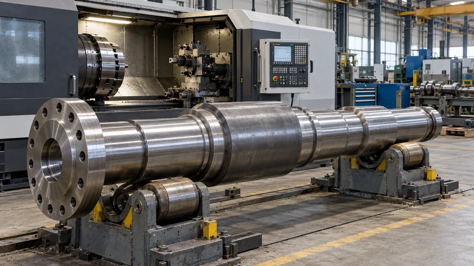
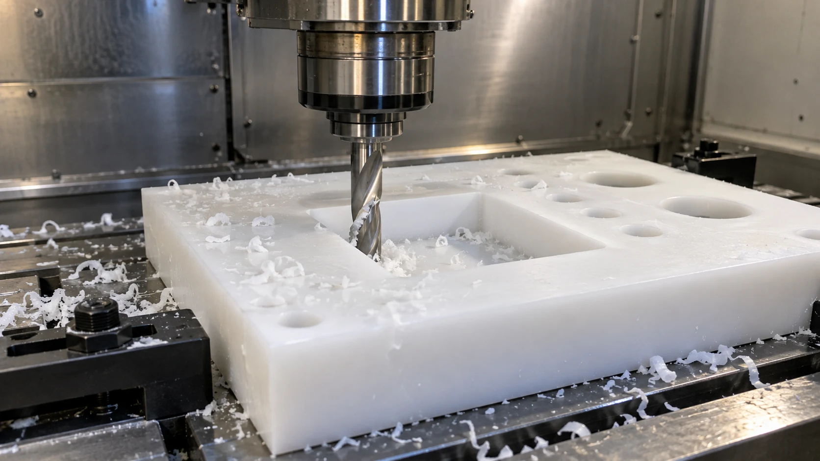
CNC milling and CNC turning can both manufacture precise prototypes, but they control different geometries and face different sources of dimensional variation. Milling is commonly used for pockets, flat surfaces, complex profiles, and hole patterns. Turning is particularly well suited to cylindrical features such as shafts, sleeves, and bearing journals.
Understanding these differences helps engineers select reasonable tolerances, avoid overengineering, and design parts that can transition from prototyping to small-batch production.
This guide compares practical CNC milling and turning tolerances, explains what affects achievable accuracy, and shows when precision grinding, reaming, or additional inspection may be necessary.
CNC Milling vs. Turning: Typical Tolerances at a Glance
For conventional CNC-machined prototypes, a general dimensional tolerance around ±0.10 mm is a useful initial planning reference for many noncritical features. Tighter tolerances, including ±0.05 mm and ±0.025 mm, are achievable on suitable features with appropriate machines, workholding, tooling, and inspection.
However, no single tolerance applies universally to an entire machined component.
A short diameter turned in a rigid setup behaves differently from a long, slender shaft. Likewise, a milled pocket in a solid aluminum block is easier to control than a thin-walled housing that deforms when released from its fixture.
Practical CNC Tolerance Comparison
| Feature or requirement | CNC milling | CNC turning |
|---|---|---|
| General dimensional features | ±0.10 mm often practical | ±0.10 mm often practical |
| Controlled precision dimensions | ±0.05 mm on suitable features | ±0.05 mm on suitable features |
| Tighter selected dimensions | ±0.025 mm or tighter after review | ±0.025 mm or tighter after review |
| Cylindrical diameters | Boring, circular interpolation, or reaming | Naturally suited to OD/ID control |
| Flatness | Face milling or finishing operations | Facing for suitable rotational parts |
| Hole position | Strong capability using defined datums | Possible for appropriate axial or live-tool features |
| Runout between diameters | Dependent on geometry and setups | Often easier to control in one setup |
| Thin-wall distortion | Important for pockets and housings | Important for rings and thin sleeves |
| Common secondary finishing | Reaming, boring, grinding, lapping | Cylindrical grinding, honing, lapping |
These values are illustrative DFM planning references, not guaranteed 6CNC tolerances or universal machine capability limits. Actual acceptance requirements must be defined in the drawing and confirmed through manufacturing review.
What Do These Numbers Mean?
A dimension of 50.00 ±0.10 mm permits a finished measurement between 49.90 mm and 50.10 mm. Reducing the tolerance to ±0.01 mm narrows the acceptable range to 49.99–50.01 mm.
That difference is substantial from a manufacturing perspective. The tighter feature may require additional finish passes, more careful temperature control, specialized inspection, or a different machining sequence.
The goal of a good prototype drawing is not to specify the smallest possible tolerance. It is to define the dimensional variation the assembly can actually tolerate.
Why CNC Milling and Turning Achieve Different Levels of Accuracy
Both processes use computer-controlled tool movement to remove material, but their cutting mechanics are fundamentally different.
A rotating cutting tool removes material from a stationary or repositioned workpiece.
The workpiece rotates while a cutting tool generates cylindrical and axial features.
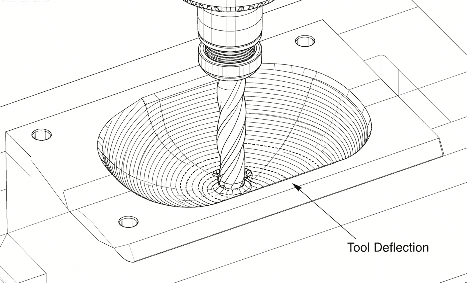
In CNC milling, dimensional accuracy depends on the relationship between the cutter, machine axes, fixturing, and part geometry. A milling tool may experience lateral deflection as it machines a wall or pocket, causing dimensional deviations or tapered surfaces.
In CNC turning, cylindrical geometry is generated relative to the machine’s rotational axis. This makes turning an efficient method for machining round features, although tool deflection, spindle condition, workholding, thermal effects, and workpiece flexibility still affect the result.
Turning is not inherently more accurate for every dimension. A milled hole finished by precision boring or reaming may achieve a tighter diameter tolerance than a difficult internal turning operation on a flexible component.
The important distinction is which process best controls the geometry that matters to the part’s function.
CNC Milling Tolerances: What Engineers Should Expect
CNC milling is widely used to manufacture prototype housings, brackets, manifolds, plates, fixtures, and other components containing nonrotational features.
Although modern machining centers offer precise positioning, the accuracy of a finished part depends on several mechanical and material-related factors. Machine positioning accuracy alone does not establish the dimensional tolerance of the part.
Tool Deflection and Wall Accuracy
When an end mill cuts along a wall, the cutting forces can bend the tool slightly away from its programmed path. The magnitude of this deflection depends on tool diameter, unsupported length, tool material, cutting force, and cutting conditions. A fixed overhang ratio such as 3:1 is not a universal threshold at which severe deflection begins.
Long, narrow tools used to machine deep pockets are particularly susceptible to deflection. This may produce a wall that is slightly tapered or a pocket that measures differently near the top and bottom.
For example, consider an aluminum prototype housing with a 45 mm deep pocket and narrow internal corners. A small-diameter end mill may be required to reach the corners, but its relatively long reach can make the final wall dimension more difficult to control.
Rather than requiring every pocket wall to meet ±0.01 mm, a better design may specify tighter tolerances only for bearing locations or mating features while allowing less critical internal surfaces greater variation.
Manufacturing strategies such as shorter tool overhang, lighter finishing cuts, suitable cutter geometry, and improved workholding can help reduce deflection.
Flatness and Thin-Wall Distortion
A milled surface may appear flat while the component is clamped, then change shape when the workholding pressure is removed.
This problem is common in thin aluminum plates, lightweight enclosures, and housings with large internal cavities. Removing material changes the balance of residual stress within the stock, and aggressive clamping can temporarily deform thin sections.
Imagine a 200 × 150 × 10 mm aluminum plate with a large pocket machined into one face. If the remaining wall is very thin, the part may move after machining even when the cutting operation itself was accurately programmed.
Achieving a demanding flatness tolerance may require balanced material removal, suitable stock, controlled clamping, intermediate stress relief where appropriate, and finish machining after roughing.
For designs requiring exceptionally flat surfaces, surface grinding or lapping may be more suitable than simply repeating milling passes.
Hole Position and Multiple Setups
Hole patterns are another common source of prototype tolerance problems.
A series of holes machined in one setup may have a relatively stable positional relationship because they share the same fixture and coordinate system. If a part must be repositioned, additional errors can arise when transferring between setups.
A precision bracket, for example, may contain two dowel holes and several clearance holes. The dowel holes establish alignment between assemblies, while the clearance holes primarily accommodate fasteners.
Applying the same tight location tolerance to every hole may increase cost without improving function.
A more practical drawing defines suitable datums, tightly controls the locating holes, and specifies reasonable clearance for ordinary mounting holes.
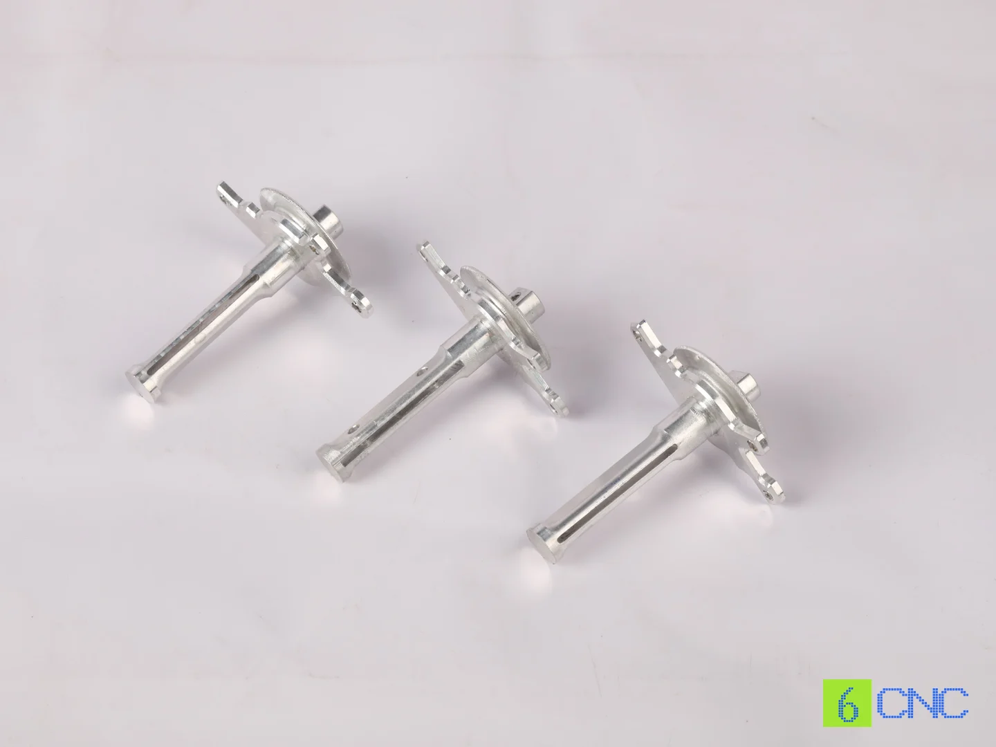
CNC Turning Tolerances: Diameters, Runout, and Roundness
CNC turning is particularly effective for rotational components such as shafts, bushings, spacers, sleeves, pins, and threaded components.
Because the workpiece rotates around a spindle axis, turning can produce multiple coaxial features efficiently when the component geometry and setup permit.
However, diameter accuracy and geometric accuracy are not interchangeable. A shaft may satisfy its diameter tolerance but still exhibit excessive runout, taper, or form error.
Controlling Shaft Diameters
For a short, rigid shaft, holding a selected diameter within ±0.025 mm may be practical with suitable equipment and machining conditions. Tighter requirements can also be evaluated, particularly when the critical feature is accessible and can be measured reliably.
Challenges increase with slender or flexible parts.
Suppose a prototype shaft is 300 mm long with a diameter of 12 mm. Even when using the same machine as a shorter shaft, cutting forces and workholding can cause the longer component to deflect.
The shaft may require a tailstock, steady rest, reduced cutting forces, or an alternate process sequence. Inspection must also distinguish between diameter error, straightness, and runout.
For long shafts, specifying a tight diameter tolerance without considering straightness and support conditions may not adequately define the component’s functional requirements.
Runout and Concentric Relationships
When several shaft diameters must rotate around a common axis, their relationship can be just as important as their individual sizes.
Machining multiple bearing journals in one setup can reduce the need for datum transfers. However, this does not automatically guarantee a particular runout tolerance. Spindle condition, workholding, part deflection, cutting forces, and measurement setup still matter.
If the shaft must be reversed to machine the opposite end, the manufacturer may need to use precision workholding, suitable locating features, or additional finishing operations to maintain alignment.
For critical rotational parts, drawings should define appropriate runout requirements relative to a clearly identified datum axis. Circular runout or total runout may be more meaningful than an ambiguous concentricity note, depending on the intended function.
Thin-Walled Turned Components
Thin-walled rings and sleeves present another challenge. Excessive chucking force can temporarily deform the workpiece, causing an apparently correct bore to become out of round after unclamping.
A thin stainless steel sleeve, for example, may be held securely during turning but recover elastically after removal from the chuck.
Soft jaws, expanding mandrels, controlled clamping force, and carefully planned roughing and finishing operations can reduce this risk. The best approach depends on wall thickness, material, diameter, and required tolerances.
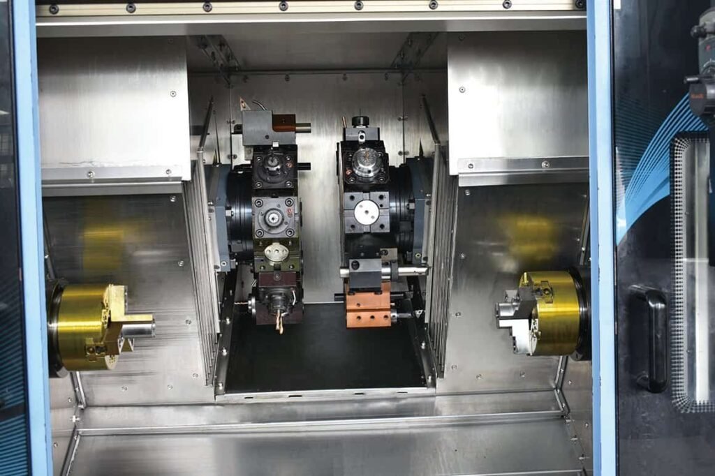
When to Use Milling, Turning, or Mill-Turn Machining
Some prototype components contain both rotational and nonrotational features. Choosing a manufacturing process based only on the overall appearance of the part may lead to unnecessary setups.
Consider a precision shaft with several diameters, a cross-drilled hole, and a milled keyway. The primary shaft geometry is best suited to turning, while the cross-hole and keyway require additional machining operations.
A conventional approach is to turn the shaft and transfer it to a milling machine. Alternatively, a mill-turn machine with live tooling may complete many of these features without removing the part.
The potential advantage of mill-turn machining is better control over setup transfers and improved process efficiency, not an automatic guarantee of tighter tolerances.
| Prototype geometry | Usually preferred process | Reason |
|---|---|---|
| Rectangular mounting bracket | CNC milling | Flat faces, pockets, drilled features |
| Cylindrical spacer | CNC turning | Concentric OD, ID, and faces |
| Hydraulic manifold | CNC milling | Multiple intersecting passages |
| Precision shaft with keyway | Turning + milling or mill-turn | Mixed rotational and milled features |
| Thin aluminum enclosure | CNC milling | Complex cavities and mounting details |
| Bearing sleeve | CNC turning, optional finishing | Bore and diameter control |
| Precision bearing journal | Turning, possible cylindrical grinding | Diameter, surface finish, and runout requirements |
The process should be selected around the most functionally important features and the manufacturing risks associated with them.
Understanding ISO 2768 and General CNC Machining Tolerances
For general tolerance types and drawing principles, read the Machining Tolerance & Accuracy Guide.
ISO 2768 is commonly referenced on engineering drawings to establish general tolerances for dimensions that do not have individually specified limits.
One important distinction is that ISO 2768 does not prescribe a single universal tolerance for every CNC-machined part. Its general dimensional tolerance classes vary according to the nominal dimension and type of feature.
For example, under ISO 2768-1, the medium (m) class provides different permissible deviations for a 20 mm dimension and a 200 mm dimension.
General Tolerances Are Drawing Requirements, Not Machine Capability
ISO 2768-1 addresses general tolerances for applicable linear and angular dimensions without individual tolerance indications. The permitted deviation depends on nominal size and tolerance class: ISO 2768-m is not a blanket ±0.10 mm requirement for every dimension. A general-tolerance note does not certify a machine or establish a supplier’s capability.
ISO 2768-2:1989 has been withdrawn and superseded by ISO 22081:2021. Do not silently reinterpret an existing drawing under a different standard; agree the edition, general-tolerancing approach, and acceptance criteria with the drawing owner. See the ISO status record.
A housing may use general tolerances for exterior dimensions and an individually specified H7 bearing bore. H7 limits depend on nominal diameter, and the correct fit depends on the application. Individually indicated requirements take precedence over the applicable general note for those features.
Dimensional Tolerances vs. GD&T
A dimensional tolerance controls the permitted variation of a feature’s size or distance. Geometric Dimensioning and Tolerancing (GD&T) addresses characteristics such as form, orientation, location, and runout.
These should not be treated as interchangeable. A flatness requirement of 0.02 mm defines a zone between two parallel planes; it is not written as ±0.02 mm. Flatness does not reference a datum, while position and runout specifications may require functional datums and appropriate modifiers.
Consider a mounting plate containing two precision dowel holes. Both holes may meet their specified diameter tolerances while being incorrectly positioned relative to the mounting datum.
Likewise, a shaft journal may measure within its diameter limits but still have unacceptable roundness or runout.
For drawings that use GD&T, the applicable system—such as ASME Y14.5 or the relevant ISO GPS standards—should be identified. Datum references and feature control frames should reflect how the part functions and will be inspected.
When Are Grinding, Reaming, or Honing Necessary?
CNC milling and turning can produce highly accurate parts, but certain features may benefit from a specialized finishing operation.
The decision should be based on the complete engineering requirement, not an arbitrary numerical threshold. A finish below Ra 0.4 µm does not always require grinding, and hardness above 45 HRC does not automatically rule out turning. Tooling, accessibility, geometry, and a qualified process must be evaluated together.
Cylindrical Grinding for Bearing Journals
A shaft may require a precise bearing fit combined with tight roundness, low runout, and a particular surface finish. Depending on material condition and feature accessibility, CNC turning may be sufficient, but cylindrical grinding is often considered for demanding or hardened bearing journals.
For a heat-treated steel shaft, a typical process may involve rough turning, heat treatment, and finish grinding. Finishing after heat treatment can help address dimensional changes introduced during thermal processing.
The choice must consider available grinding allowance, shaft rigidity, and the inspection requirements.
Reaming and Precision Boring for Holes
For precision holes in milled components, drilling alone may not provide the required dimensional accuracy and surface condition.
Reaming is commonly used to finish an existing hole to a controlled size. Precision boring offers another option, particularly where hole position, diameter, or geometry needs careful adjustment.
A prototype housing with a 12 mm dowel hole, for example, may be drilled undersize and reamed to its specified fit tolerance.
However, reaming primarily follows an existing hole and does not necessarily correct substantial positional error. The drilling and positioning strategy must therefore be appropriate before the finishing operation begins.
Honing for Critical Internal Surfaces
Honing can improve bore size, form, and surface characteristics for suitable internal cylindrical features. It is used in applications where the functional requirements justify a dedicated finishing process.
Hydraulic components are a useful example. A precision bore may require controlled roundness, diameter, and surface texture to support proper sealing or sliding behavior.
Nevertheless, neither a particular surface roughness value nor a small diameter tolerance automatically makes honing mandatory. Precision boring, grinding, or another qualified process may satisfy the same functional requirement.
How Material Choice Affects CNC Prototype Tolerances
The selected material influences cutting forces, dimensional stability, workholding, tool wear, and the possibility of distortion.
Two prototype parts with identical geometry and drawing tolerances may require different machining strategies if one is made from aluminum and the other from stainless steel or engineering plastic.
| Material | Typical tolerance-related concern | Manufacturing consideration |
|---|---|---|
| Aluminum 6061-T6 | Thin-wall deformation, residual stress | Controlled clamping and balanced material removal |
| Aluminum 7075-T6 | Distortion in highly relieved geometries | Stock condition and machining sequence |
| Stainless Steel 304 | Work hardening, cutting heat, tool wear | Suitable tooling and cutting parameters |
| Stainless Steel 316 | Cutting forces, tool wear, thermal effects | Process planning and finishing passes |
| AISI 4140 | Material hardness and heat-treatment condition | Tool selection and finishing sequence |
| Titanium Grade 5 | Heat concentration and workpiece flexibility | Rigid tooling, controlled cutting conditions |
| POM / Acetal | Thermal expansion, clamping deformation | Temperature and fixture control |
| PEEK | Thermal behavior, stock stress, dimensional movement | Material conditioning and stable machining |
For example, an aluminum enclosure containing deep pockets may distort as material is removed, even when machining accuracy is otherwise good. A similar enclosure in stainless steel may present different challenges related to cutting forces, tool wear, and surface condition.
Engineering plastics introduce additional considerations because their thermal expansion and mechanical behavior can differ substantially from metals.
For tight-tolerance prototypes, the material’s supply condition and dimensional stability should be evaluated alongside its mechanical properties.
Three Practical Examples of Prototype Tolerance Selection
The following examples illustrate how tolerances can be assigned according to functional requirements. These examples explain design choices rather than measured process capability.
Example 1: Aluminum Sensor Housing
Part: Aluminum 6061-T6 sensor housing
Process: CNC milling
Challenge: Maintaining mounting alignment without unnecessarily tightening every pocket and exterior dimension.
A sensor housing may contain a rectangular cavity, four mounting holes, and two precision locating holes. The exterior dimensions do not necessarily require the same precision as the locating features.
A suitable drawing might apply relatively broad general tolerances to noncritical surfaces while separately defining the locating-hole sizes, positions, and mounting-face flatness.
The manufacturing plan can prioritize these functional features, using the selected datum surfaces for machining and inspection.
This reduces the risk of spending additional machining time on dimensions that have little influence on the assembled product.
Example 2: Stainless Steel Precision Shaft
Part: Stainless steel stepped shaft
Process: CNC turning
Challenge: Controlling bearing journal diameters and runout across several cylindrical features.
A precision shaft may contain two bearing journals, a threaded end, and a shoulder used for axial location.
The engineering drawing should distinguish the requirements for each feature. The bearing journals may need specified fits and runout relative to an appropriate datum axis, while a noncritical shaft section may use a general dimensional tolerance.
Where possible, machining related journals in one setup can help reduce alignment uncertainty. The completed shaft should then be inspected using methods appropriate to the specified size and geometric requirements.
If the material condition or functional requirements exceed a practical turning process, cylindrical grinding may be considered.
Example 3: Thin-Walled Robotic Bracket
Part: Lightweight aluminum robotic bracket
Process: CNC milling
Challenge: Preventing thin-wall movement and maintaining critical mounting geometry.
A lightweight robotic bracket may combine deep pockets, thin ribs, and multiple mounting locations. The design reduces weight, but it also makes the component more sensitive to clamping pressure and material removal.
A drawing specifying ±0.01 mm on every wall and pocket dimension may create substantial manufacturing difficulty without improving performance.
A better approach is to identify the surfaces that establish assembly alignment, control their geometry appropriately, and allow reasonable variation in weight-reduction features.
The manufacturer can then plan roughing, workholding, and finishing around the component’s functional requirements.
Why Tighter CNC Tolerances Increase Prototype Costs
Tighter tolerances often increase manufacturing cost because they reduce the acceptable variation in the finished component.
The relationship is not linear. Reducing a tolerance from ±0.10 mm to ±0.05 mm may have little effect on a simple feature in a stable setup, while reducing it to ±0.005 mm may require a fundamentally different manufacturing and inspection approach.
Several cost drivers contribute to this difference.
Additional machining operations. Tight features may need separate roughing and finishing passes, specialized cutters, or secondary processes.
More demanding workholding. Maintaining accurate geometry across multiple setups may require custom soft jaws, fixtures, or additional locating operations.
Increased inspection requirements. A narrow tolerance band may require more capable measurement equipment, additional inspection time, or stricter environmental control.
Greater manufacturing risk. When fewer parts are acceptable, changes in tool wear, temperature, or material movement may result in additional rework or rejected components.
Higher setup cost per part. Prototype quantities are often too small to distribute specialized setup and inspection costs across many units.
The most effective way to manage these costs is to assign precision selectively.
How to Specify Realistic Tolerances on Prototype Drawings
An effective prototype drawing should communicate manufacturing intent clearly enough that the supplier can choose a process and verify the finished part without unnecessary assumptions.
Prototype Tolerance Checklist
-
Identify the features that control assembly, movement, or sealing.
-
Apply general tolerances to noncritical dimensions.
-
Specify fits for bearing seats, shafts, and precision holes.
-
Define functional datums and geometric tolerances where needed.
-
Review thin walls, long tool reach, and slender components.
-
Account for finishing, coatings, and heat treatment.
-
Specify inspection and documentation requirements.
-
Have the manufacturer review unusually tight requirements before production.
In addition to dimensions, the drawing should identify the material grade, required surface finish, applicable standards, and any processes that may change the final geometry.
If a tight tolerance is required only on one feature, communicate that requirement explicitly rather than applying a general ±0.01 mm tolerance across the entire part.
This makes it easier for a machining supplier to evaluate feasibility, identify risk, and quote an appropriate manufacturing method.
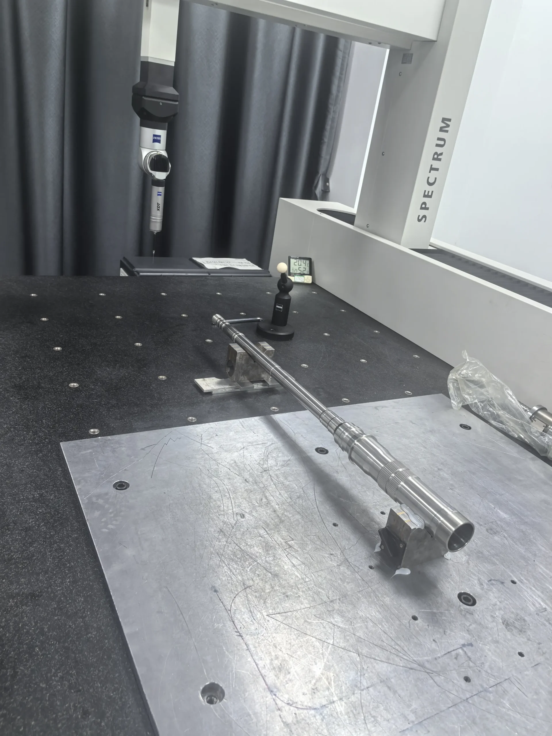
Inspection Resolution Is Not Measurement Uncertainty
An instrument’s display resolution does not establish its measurement uncertainty or the tolerance a finished part can reliably meet. Calibration, measurement method, datum setup, temperature, and part condition all affect the result. Agree suitable inspection and acceptance criteria before manufacturing. Also define whether dimensions apply before or after coatings and heat treatment.
One conforming prototype does not demonstrate stable production capability. For repeat batches, agree a controlled process and inspection plan, with capability evidence where the application requires it.
How 6CNC Supports Tight-Tolerance Prototypes
At 6CNC, prototype manufacturing begins with understanding the drawing and the role of each critical feature.
Our team can review suitable CNC milling, CNC turning, and precision finishing routes for the component geometry and drawing requirements.
For prototypes with demanding dimensional requirements, our engineering and quality teams can review material selection, workholding, machining sequences, surface finish requirements, and inspection methods before production.
The inspection plan should identify appropriate dimensional, geometric, and surface-texture checks. Equipment, method, reporting scope, and measurement uncertainty must be appropriate to the specified acceptance criteria.
Where specialized finishing is needed, the machining plan can incorporate appropriate secondary operations. Actual tolerance capability and inspection arrangements are confirmed based on the component geometry, material, quantity, and specified acceptance criteria.
Whether you need a single engineering prototype or a repeat order of small-batch custom parts, our team can evaluate your drawings and provide manufacturing feedback.
Need help determining whether your prototype tolerances are practical?
Send your 2D drawing, 3D CAD model, material specification, and required quantity to 6CNC. Our team can review critical dimensions and discuss suitable manufacturing options before quotation.
Request a Prototype CNC Machining Quote.
Discuss inspection and quality documentation
Frequently Asked Questions
Is CNC turning more accurate than CNC milling?
Not universally. Turning is particularly suitable for cylindrical features, while milling is effective for flat surfaces, pockets, and complex hole patterns. Achievable accuracy depends on part geometry, equipment, tooling, workholding, material, and inspection requirements.
Is ±0.01 mm achievable with CNC machining?
Yes, selected dimensions may be achievable within ±0.01 mm under suitable conditions. However, this tolerance should not be assumed for every feature, material, or geometry. A manufacturing review is recommended before including it on a prototype drawing.
What is a realistic tolerance for CNC-milled aluminum prototypes?
A tolerance around ±0.10 mm is a useful general planning reference for many noncritical features. Tighter values such as ±0.05 mm or ±0.025 mm may be practical on selected features, depending on their size, geometry, and machining conditions.
Can CNC turning achieve a ±0.005 mm diameter tolerance?
Such tolerances may be possible in specialized turning applications, but they should be treated as demanding requirements requiring process and inspection review. Grinding or another finishing operation may offer a more suitable manufacturing route for certain materials and geometries.
Does ISO 2768 guarantee CNC machining accuracy?
No. ISO 2768 establishes general tolerance requirements for applicable drawing dimensions. It does not certify machine accuracy or guarantee that a particular supplier can achieve those values on every component.
What is the difference between dimensional tolerance and surface roughness?
Dimensional tolerance controls the allowable variation in size or geometry, while surface roughness describes aspects of the surface texture. A component can meet a dimensional tolerance while failing its roughness requirement, or vice versa.
How can I reduce the cost of tight-tolerance CNC prototypes?
Apply tighter tolerances only to functionally important features, use suitable datums and fits, avoid unnecessary precision on cosmetic surfaces, and review challenging geometry with the manufacturer before machining.