
A CNC quote can look straightforward until the drawing leaves room for interpretation. That is usually where cost, delay, and scrap start. If you want to know how to prepare CNC drawings well, think less about making the print look complete and more about making it unambiguous for machining, inspection, and purchasing.
We see the same pattern across prototypes, pilot runs, and low-volume production. A part can be perfectly modeled in CAD and still create problems on the shop floor if the drawing does not define what actually matters. Good CNC drawings shorten review time, reduce back-and-forth, and protect the features that affect fit, function, and assembly.
What CNC drawings need to achieve
A CNC drawing is not just a record of shape. It is a manufacturing instruction and an inspection reference. Your machinist uses it to decide workholding, tool access, setups, and process sequence. Your supplier uses it to price risk. Your quality team uses it to verify acceptance.
That is why over-dimensioned drawings and under-defined drawings both cause trouble. Too many unnecessary callouts slow programming and inspection. Too few critical requirements force assumptions. The right drawing gives enough control to make the part repeatably, without specifying details that do not affect the result.
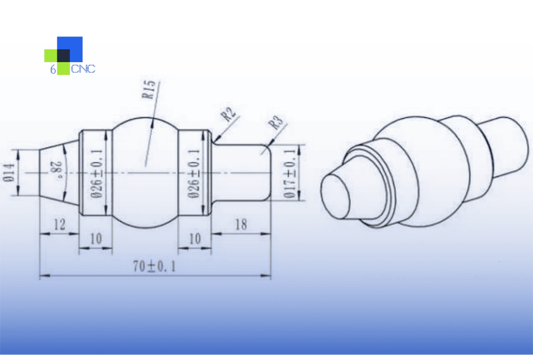
For most machined parts, your drawing should answer six questions clearly. What is the material? Which dimensions are critical? What tolerances apply? How should holes, threads, and surface finish be produced? Which datums control inspection? What cosmetic or post-processing requirements matter?

How to prepare CNC drawings for real production
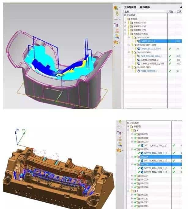
Start with the 3D model, but do not stop there. The model carries geometry. The drawing carries intent. If your buyer sends only a STEP file, the supplier can machine it, but the quote may include wider assumptions on tolerance and finish. That often increases cost or creates revision questions.
A production-ready drawing usually includes the part name or number, revision, units, projection method, material, quantity, finish, general tolerances, and all feature-specific tolerances that differ from the default. Keep the title block disciplined. Missing revision control alone can create expensive mix-ups during engineering changes.
Dimension from function, not from convenience. If a pocket locates a bearing, dimension it from the datum scheme that matches the assembled condition. If a hole pattern mates to another component, control hole position from the mounting faces and primary locating surfaces. Chaining dimensions across multiple features may look neat, but it stacks variation. Baseline dimensions usually serve machining and inspection better.
Datums deserve more attention than they often get. A datum structure tells the shop which surfaces matter first. On precision parts, this choice affects setup strategy and CMM results. Pick stable, accessible features that reflect how the part is actually located in service. If the part seats on a base and aligns against a side face, those surfaces should probably lead the datum scheme.
Tolerances: be precise, but only where needed
Tight tolerances drive cost faster than many buyers expect. A jump from plus or minus 0.1 mm to plus or minus 0.01 mm can change tool strategy, setup time, inspection method, and scrap risk. Very tight controls, such as ±0.002 mm, are possible on the right geometry and process, but they should be reserved for features with a real functional reason.
General tolerances help keep the drawing clean. Feature-specific tolerances should be used where fit, sealing, bearing alignment, or assembly location depends on them. If every dimension carries a tight limit, the supplier must treat the whole part like a critical feature. That raises price and lead time, even when only two surfaces actually matter.
Geometric tolerancing can help, but only when it is applied correctly. Position, flatness, perpendicularity, and concentricity are useful because they define allowable variation more accurately than coordinate dimensions alone. Still, unnecessary GD&T can overcomplicate simple parts. Use it where functional control matters, especially for hole patterns, mating faces, and rotating features.
A practical rule works well here. Tighten what affects performance, inspection, and interchangeability. Relax what does not. That is the fastest path to a stable quote and a part that does not carry hidden manufacturing cost.
Call out holes, threads, and machined features clearly
Hole notes are one of the most common sources of delay. A drawing should state diameter, depth, quantity, tolerance if critical, and whether the hole is through or blind. Counterbores, countersinks, and spotfaces need the same level of detail. If you leave depth to the model only, the shop may still ask for confirmation.
Threads should include standard, size, pitch, class if required, and thread depth or through condition. If thread quality matters for sealing or repeated assembly, say so. If it does not, avoid over-specifying inspection requirements that add cost without improving function.
Radius and chamfer callouts should also be intentional. General edge breaks are often better handled through a note such as deburr and break sharp edges than by dimensioning every corner. If one edge condition is critical for assembly or safety, call that feature out directly.
Deep pockets, thin walls, and small internal radii deserve special attention. These are not just geometric features. They are process-risk features. A deep narrow pocket may require long tools and reduced feeds, which affects finish and cycle time. A tiny internal corner radius may force EDM or a much smaller cutter than expected. Your drawing does not need to prescribe the method, but it should avoid impossible geometry and should flag functionally critical conditions.
Surface finish, material, and secondary operations
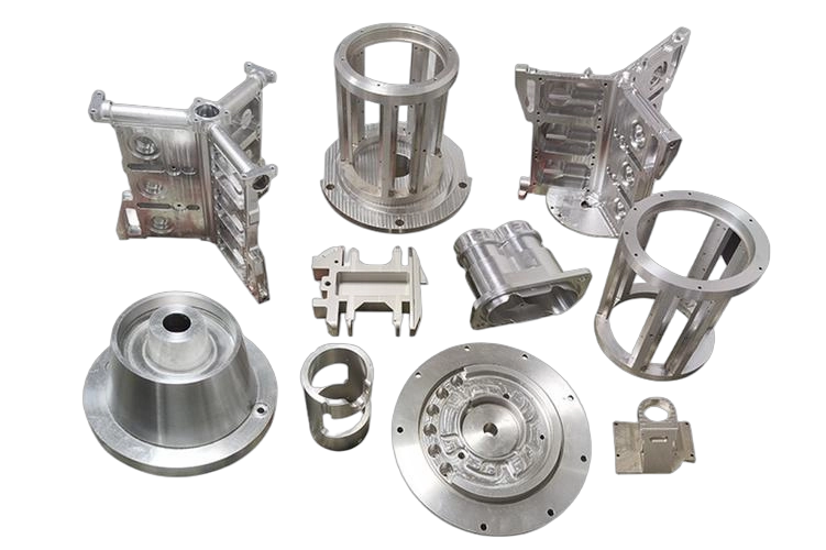
A part drawing is incomplete if the material is vague. Aluminum 6061 and 7075 do not machine and perform the same way. Stainless 303 and 304 differ in machinability. Engineering plastics can move during machining and inspection depending on moisture and temperature. If your project requires certification, hardness, grain direction, or specific stock condition, state it.
Surface finish should be tied to function. Sealing faces, sliding surfaces, optical interfaces, and cosmetic faces often need different requirements. Use roughness values where necessary. Do not assign a fine finish across the entire part unless the application truly needs it. Extra finish control usually means extra operations.
Secondary operations belong on the drawing or in a clearly linked manufacturing note. Anodizing, plating, heat treatment, passivation, bead blasting, laser marking, and grinding can all affect dimensions or masking needs. If a bore must remain within tolerance after anodizing, that condition must be defined before production starts.
Common drawing mistakes that create quote risk
The first is conflicting information between the 3D model and the 2D print. If the model shows one geometry and the drawing implies another, most suppliers will stop and ask. Some will quote to the more conservative interpretation. Neither outcome helps your timeline.
The second is missing critical dimensions because the designer assumes the CAD model is enough. The shop may be able to infer the geometry, but inspection may not know which features define acceptance. A complete drawing identifies what will be checked and how tightly.
The third is using blanket notes that do not match the part. “Machine to drawing” or “remove all burrs” is fine as a general note, but it does not replace specific callouts for delicate edges, press fits, or cosmetic surfaces.
The fourth is tolerancing the drawing for the ideal design, not the real process. It depends on material, feature size, machine access, and quantity. A tolerance that is reasonable on a ground shaft may be expensive on a milled wall. This is where early DFM feedback saves time.
A practical review before release
Before sending a drawing for quote, check it like a supplier will. Can a machinist identify the datums, critical features, and likely setup sequence? Can a quality inspector measure every controlled feature with standard tools or CMM access? Can a buyer compare suppliers on the same assumptions?
We recommend one final pass with three lenses. Functional lens: do the tolerances match real assembly needs? Manufacturing lens: are any features difficult, risky, or undefined? Commercial lens: will this drawing create unnecessary cost because too many requirements are tighter than needed?
If your team works on prototypes, leave room for iteration. Early builds often benefit from clear critical dimensions plus sensible general tolerances rather than fully constrained prints everywhere. As the part moves toward repeat production, lock down the features that proved sensitive in testing.
At 6 CNC, we have seen well-made drawings cut days from engineering review and prevent avoidable nonconformance on low-volume precision parts. The goal is not a perfect-looking print. The goal is a drawing that tells the shop exactly what success looks like, the first time.