A part can look clean in CAD and still become expensive, slow, or unstable once it reaches the shop floor. We see this often with prototype and low-volume production parts. The design works in theory, but small geometry choices create extra setups, custom tools, inspection challenges, or scrap risk. That is exactly where dfm for cnc machining matters.
Design for manufacturability is not about simplifying a part until it loses function. It is about shaping the design so your machinist can produce it accurately, repeatedly, and at a reasonable cost. For engineering teams and buyers, that translates into fewer quote revisions, shorter lead times, more predictable quality, and fewer late-stage surprises.
What dfm for cnc machining really means
In CNC work, DFM means checking whether a part matches the realities of cutting tools, workholding, machine access, material behavior, and inspection methods. A model may be technically machinable, but still inefficient to produce. That difference is where cost and risk accumulate.
Take an internal corner with a perfect 90-degree edge. The CAD model may require it, but an end mill leaves a radius unless you add extra operations such as EDM or a very small tool. That one detail can change cycle time dramatically. The same is true for deep narrow pockets, very thin walls, or callouts that demand tight tolerance across every feature whether the assembly needs it or not.
Good DFM asks practical questions early. Can we reach this feature with a standard tool? Can we hold this tolerance in one setup? Will the part distort after material removal? Can the inspector verify the geometry efficiently? If the answer is no, the drawing needs adjustment before production starts.
Why DFM affects more than part price
Most teams think about DFM as a cost exercise. Cost is part of it, but the bigger impact is project control. A part with poor manufacturability often triggers back-and-forth during quoting, slower process planning, more operator intervention, and higher inspection load. Those issues stretch lead time even before the first chip is cut.
There is also a quality consequence. Tight features placed in hard-to-reach areas are harder to machine consistently. Thin sections can chatter or deform. Overly aggressive material removal can release stress and move dimensions out of spec. In production, those risks become yield loss.
For buyers, the result is familiar: the first quote looks acceptable, then revisions appear after engineering review, delivery moves out, and the part arrives with exceptions or rework notes. Strong DFM reduces that pattern because the manufacturing plan is stable from the start.
The design choices that matter most
Tolerances should follow function
The fastest way to overbuild a CNC part is to apply tight tolerances everywhere. If a feature does not affect fit, sealing, alignment, or motion, it usually does not need precision beyond standard machining capability. General tolerances are often enough for non-critical faces and cosmetic geometry.
We advise customers to reserve tight tolerances for true functional features. A bore for a bearing seat may need close control. An outside face that never mates with another part usually does not. This distinction matters because holding ±0.01 mm on one critical feature is manageable. Holding it across the entire part increases machine time, inspection effort, and scrap risk.
If you need very tight limits, define datums clearly and dimension from them logically. That gives the machinist and inspector a usable reference system instead of a drawing full of chained dimensions that stack error.
Internal corners need realistic radii
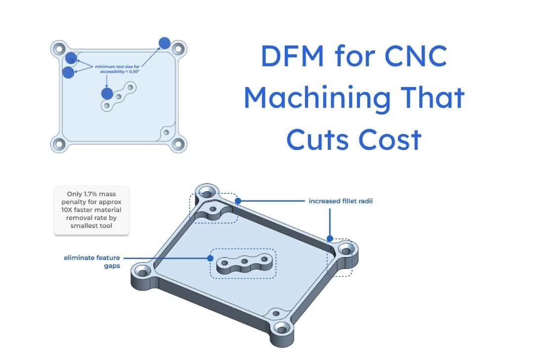
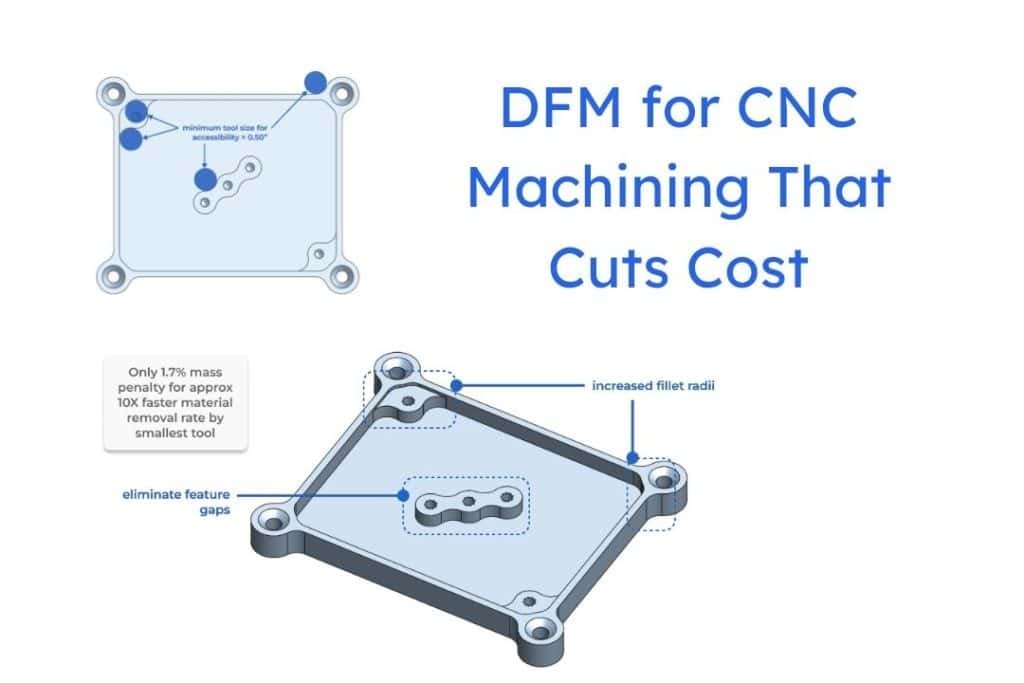
CNC tools are round. Internal corners are not. That simple fact drives many DFM changes. If you design a pocket with square internal corners, the part may require a smaller tool, extra cycle time, or a secondary process.
A larger internal radius usually improves manufacturability immediately. It lets us use a stronger tool, cut faster, and maintain better tool life. As a rule, corner radii should be slightly larger than standard end mill sizes where function allows. Even a small increase can reduce machining time.
If a mating component truly needs a sharp internal corner, consider redesigning the assembly interface. Reliefs, dog-bone corners, or a change in mating geometry often solve the problem with less cost than forcing the machined part to do something unnatural.
Deep pockets and small features raise risk
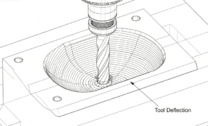
Feature depth-to-width ratio is one of the clearest indicators of machining difficulty. Deep narrow pockets restrict tool access and increase deflection. The result can be chatter, poor finish, taper, or long cycle times due to reduced feed rates.
Small slots and thin ribs create similar problems. A tool that is small enough to enter the geometry is also less rigid. That affects both accuracy and productivity. In aluminum, the process may still be manageable. In stainless steel or titanium, the same feature becomes much less forgiving.
If the function allows it, widen the pocket, reduce depth, or split the part into simpler components. Those changes can save days in process development and make dimensional results more consistent.
Wall thickness needs balance
Thin walls often look efficient in CAD. In machining, they can vibrate during cutting or spring after the tool passes. That movement affects flatness, position, and surface finish. Material type matters here. A thin aluminum wall behaves differently from a thin wall in PEEK or stainless steel.
There is no single wall thickness rule for every material and geometry. The practical rule is this: the thinner the wall, the more carefully the process must be planned. That can mean roughing and finishing in separate steps, leaving support material longer, or accepting slower machining. If your design can tolerate thicker sections, production becomes easier and more repeatable.
DFM for CNC machining starts with process selection
A good DFM review is not only about the shape of the part. It also asks whether the chosen process fits the geometry and volume. A milled block, a turned part, a 5-axis setup, or a mill-turn process each changes what is efficient.
For example, a rotationally symmetric part with cross-holes may look like a milling job in CAD, but turning the main profile first can cut cost and improve concentricity. A complex housing with features on multiple faces may justify 5-axis machining because fewer setups reduce cumulative error. On the other hand, 5-axis is not automatically cheaper. If the geometry is simple, a 3-axis process with smart fixturing can be the better choice.
This is where supplier feedback matters. The same design may have two viable process routes, and the best one depends on tolerance distribution, material, batch size, and inspection plan.
Material choice changes manufacturability
Material selection often starts with strength, weight, corrosion resistance, or temperature performance. That is correct, but it should not end there. Different materials machine very differently.
Aluminum grades usually support faster cutting and lower tool wear. Stainless steels tend to generate more heat and work-harden. Titanium adds cost through slower machining and shorter tool life. Engineering plastics may machine quickly, but thermal movement and burr control can affect tolerance strategy.
If two materials both satisfy the application, the easier-to-machine option often lowers total project cost. It may also improve delivery reliability. That trade-off is worth discussing early, especially for prototypes that need to move quickly into testing.
Drawing quality is part of DFM
Some manufacturability problems start with the drawing rather than the model. Missing datum structure, conflicting tolerances, undefined surface finish, or notes copied from older projects can all delay quoting and production.
A clean drawing tells the machine shop what matters most. It separates critical dimensions from standard ones. It avoids duplicate or contradictory callouts. It specifies thread standards correctly. It identifies surfaces that require finish, sealing, or cosmetic control.
This is especially important for global sourcing. Clear documentation reduces interpretation risk across engineering, production, and quality teams.
Where early DFM review saves the most time
The best time for DFM is before release, not after a nonconformance report. We recommend reviewing CNC parts at three points: during concept selection, before RFQ, and after first article feedback.
At concept stage, the goal is to avoid geometry that locks you into expensive processing. Before RFQ, the goal is to clean up tolerances, notes, and ambiguous features. After first article, the goal is to refine the design based on actual machining and inspection data.
In our experience, early DFM is most valuable on parts with tight tolerances, multiple setups, difficult materials, or low-volume demand where tooling amortization is limited. Those are the jobs where small design changes create the biggest payoff.
A useful DFM conversation should produce concrete outcomes. You should know which features drive cost, which tolerances are critical, which can be relaxed, and what process route supports your schedule. If that discussion does not happen, the quote may hide risk instead of removing it.
At 6 CNC, we treat DFM as part of making precision practical. A good part design should not only function in assembly. It should move through machining, inspection, and delivery without forcing avoidable cost into your project. If you can get that alignment early, everything after it gets easier.

![Comparison of Operating Principles: This figure illustrates a microscopic comparison of the surface waviness and residual scallop height generated by a face milling cutter and a ball-nose cutter under different stepover and step-down settings. [Figure 4-1]](https://6-cnc.com/wp-content/uploads/2026/06/image-2-300x199.png)