In precision CNC manufacturing, the term “Design for Manufacturability” (DFM) is frequently thrown around as a buzzword for cost reduction. However, experienced production engineers know that the truest test of a DFM-optimized part lies in one highly specific metric: the amount of manual benchwork required after the part leaves the machine.
Manual deburring is a silent killer of manufacturing margins. It introduces human variability, extends lead times, elevates scrap rates due to accidental tool slips, and relies heavily on an increasingly scarce skilled labor pool. When an engineer designs a feature that forces an operator to spend 15 minutes with a handheld scraping knife or a dental pick under a microscope, that design has failed the test of modern manufacturing efficiency.
The most profitable approach is to eliminate manual deburring entirely during the product development and CAD design stages. By implementing standardized edge-breaks, aligning geometries with standard cutting tool characteristics, and establishing smart tolerance tiers, designers can ensure that components are finished mechanically on the machine. This comprehensive guide breaks down the actionable DFM principles required to achieve a zero-manual-deburring workflow.
1. Tool-Centric Geometry: Aligning Features with Standard End Mills
The first line of defense against manual post-processing is ensuring that every feature on the component can be reached, cleared, and swept by standard, rigid cutting tool geometries. When part geometry ignores cutter physics, it forces custom tooling or, worse, manual hand-finishing.
Pocket Corner Fillets vs. Cutter Radii
A classic DFM error is designing a square internal pocket or specifying an internal corner radius that exactly matches the radius of the milling cutter. For example, if a drawing calls out a $3.0\text{ mm}$ internal corner radius, a junior CAM programmer might select a $6.0\text{ mm}$ diameter end mill ($3.0\text{ mm}$ radius) to machine the pocket.
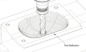
As the end mill enters the corner, the tool’s engagement angle jumps instantly from a controlled linear cut to a massive $90^\circ$ wrap-around engagement. This sudden volumetric overload causes severe tool deflection, structural chatter, and micro-tearing at the base of the corner. The resulting finish is riddled with “rework marks” and stubborn corner burrs that a machine cannot easily clean up, leaving them for a manual operator to grind out.
The DFM Rule of Thumbs for Fillets
Always design internal corner fillets to be at least $10%至15%$ larger than the radius of the intended cutting tool.
- If a $6.0\text{ mm}$ diameter end mill is standard for the pocket depth, specify an internal corner radius of $3.5\text{ mm}$ or greater.
- This allows the tool path to follow a smooth, continuous fluid arc through the corner rather than a jarring pivot. The tool maintains a constant chip load, eliminates chatter-induced burrs, and allows the machine to achieve a pristine surface finish straight from the spindle.
Tool Length-to-Diameter ($L/D$) Ratios
Deep, narrow pockets and high walls require long-reach tools. The deflection of a cylindrical cutting tool under a constant cutting force is proportional to the cube of its extension length:
$$Y = \frac{F \cdot L^3}{3 \cdot E \cdot I}$$
Where $L$ is the tool overhang length and $D$ is the tool diameter (affecting the area moment of inertia $I$).
| Overhang Ratio ($L/D$) | Structural Rigidity Risk | Dominant Surface Defect Profile | Deburring / Post-Processing Remediation |
|---|---|---|---|
| $\le 3:1$ | Minimal Deflection (Ideal) | Clean shear, excellent surface finish, zero micro-tearing. | None. Part goes straight to inspection. |
| $4:1$ to $5:1$ | Moderate Deflection | Light chatter marks along walls; minor exit burrs at floor intersections. | Automated: Can be cleared via a light high-speed finishing pass or automated tumbling. |
| $> 5:1$ | Severe Deflection & Harmonics | Heavy wall scuffing, micro-fissures, jagged floor-to-wall fillets, extreme exit flashing. | Critical Manual Work: Requires extensive manual hand-sanding or orbital polishing to clear waviness. |
To eliminate manual sanding of wall scuffs, enforce a maximum wall-depth-to-tool-diameter ratio of $3:1$ for titanium/stainless steel and $4:1$ to $5:1$ for aluminum.
2. Edge-Break Standards: Designing for In-Machine Chamfering
If a drawing states a blanket note such as "All sharp edges must be deburred," it abdicates engineering responsibility to the shop floor. The operator will likely use a manual deburring tool, resulting in inconsistent edge qualities. Instead, edges must be designed to be broken mechanically via standard 45-degree chamfers or corner-rounding tools directly on the CNC machine.
Unmachinable Edge (90-Degree Sharp):
      |
      |
======+ (Burr forms here as tool exits)

Machinable Edge (Pre-Modeled DFM Chamfer):
      |
     /  <-- 45-Degree modeled chamfer (Machine sweeps this in seconds)
====+
Modeled vs. Unmodeled Edge Breaks
Whenever possible, explicitly model 45-degree chamfers into your 3D CAD files. For external features, a $0.2\text{ mm}$ to $0.5\text{ mm}$ modeled chamfer allows CAM software to automatically recognize the geometry and generate a high-speed chamfering or profiling toolpath using a standard spot drill or chamfer mill.
If modeling every micro-chamfer degrades CAD performance on massive assemblies, you must use precise drawing callouts that define a standard, machinable dimension rather than a vague verbal instruction.
Standardized Drawing Callout Examples
To ensure edge breaks are performed inside the CNC envelope, replace ambiguous phrases with quantitative, industry-standard ISO 13715 edge symbols or precise linear dimensions.
- Incorrect Callout:
Remove all burrs.(Guarantees manual benchwork). - Correct Linear Callout:
All external edges to be chamfered 0.2mm - 0.4mm x 45°.(Allows the machinist to program a standard tool to sweep the perimeter). - Correct Chamfer Range Callout:
0.3mm MAX corner break permitted. - ISO 13715 Standard Symbol Callout:
$$\begin{array}{c} \text{–0.1} \ \boxed{\ \ \ \ \ \ } \ \text{–0.3} \end{array}$$
(This specific symbol indicates a detaching material requirement, dictating a machined undercut/burr-free zone between $-0.1\text{ mm}$ and $-0.3\text{ mm}$, completely eliminating heavy protrusion).
3. High-Risk Features: Geometries That Trigger Destructive Handwork
Certain structural features are highly prone to generating massive, inaccessible burrs during cutting. Recognizing these high-risk areas during the DFM phase allows you to alter the design before it hits the factory floor.
Thin-Walled Sections and Structural Flashing
When machining parts with very thin walls (e.g., aerospace structural ribs or electronic enclosures with wall thicknesses under $1.0\text{ mm}$), the material lacks the structural rigidity to withstand the radial forces of an end mill.
As the tool passes, the thin wall flexes away from the cutting edge. Instead of cleanly shearing the metal, the tool pushes the topmost layer of material over the wall edge, creating a massive, flexible flap of metal known as flashing.
Thin Wall Flexing Under Cutting Force:
     Tool Force --->
         \       | |  <-- Thin Wall bends away
          v      | |
                 / /
                /_/   <-- Material plows and rolls over into flashing
Because this flashing is flexible, subsequent high-speed machining passes cannot cut it off—it simply bends out of the way. The only way to remove it is for an operator to sit with a razor blade and manually slice the flashing off each rib.
- DFM Remedy: Maintain a minimum wall thickness-to-height ratio of $1:10$ in aluminum. If a rib is $10\text{ mm}$ tall, ensure it is at least $1.0\text{ mm}$ thick to provide the structural support needed for clean, burr-free shearing.
Unmachinable Blind Blind-Holes and Intersecting Tunnels
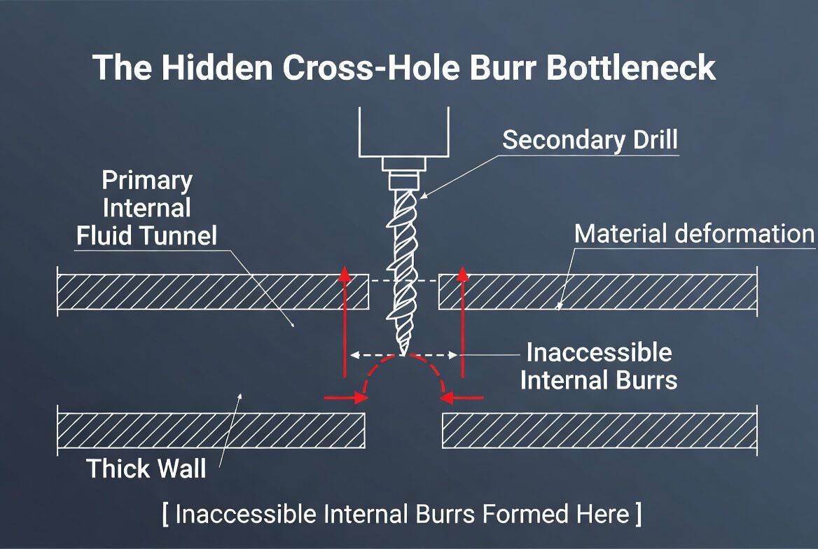
When a small lubrication internal channel or sensor cross-hole breaks into a primary cylinder, a hidden burr is formed inside the cavity. If the exit intersection occurs deep inside a block, standard mechanical deburring tools cannot reach it.
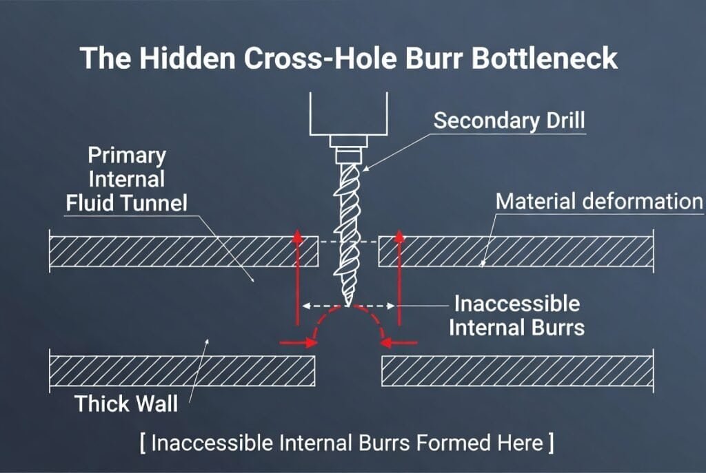
To eliminate manual wire-brushing or expensive chemical deburring for these features, apply the following structural redesigns:
- Modify the Intersection Angle: Ensure internal holes intersect at a strict $90^\circ$ perpendicular angle whenever possible. Avoid acute angle intersections (e.g., $30^\circ$ or $45^\circ$), which create long, razor-thin, knife-like edge profiles that are highly prone to massive tearing.
- Incorporate External Relief Pockets: If an internal cross-hole must break into a cavity, design an external access window or a stepped relief bore. This allows standard automated deburring tools (like a retractable ball-end mill) direct line-of-sight access to clear the intersection automatically.
4. Tolerance Tiers: What Truly Requires High-Cost Grinding?
A major driver of excessive post-processing is over-tolerancing. Specifying extremely tight geometric and dimensional tolerances across non-critical faces forces the manufacturing team to use specialized finishing operations—such as surface grinding, cylindrical honing, or manual hand-lapping—when standard milling could have sufficed.
To maximize efficiency, engineers should segregate part dimensions into three strict Tolerance Tiers, matching surface roughness ($R_a$) and dimensional requirements to specific, cost-effective machining capabilities:
| Tier | Description / Process | Linear Tolerance | Surface Roughness (Ra) |
|---|---|---|---|
| Tier 1: Ultra-Precision | Honing / Grinding / Manual Lapping | ±0.002 mm | 0.2–0.4 μm |
| Tier 2: Standard Precision | Direct CNC Milling & Turning | ±0.05 mm | 0.8–1.6 μm |
| Tier 3: Commercial Clearance | In-Machine Roughing / Vibratory Tumbling | ±0.25 mm | 3.2–6.3 μm |
Tier 1: Ultra-Precision / Critical Sealing & Bearing Interfaces
- Dimensional Range: Linear tolerances of $\pm0.002\text{ mm}$ to $\pm0.005\text{ mm}$.
- Surface Roughness: $R_a\ 0.2\ \mu\text{m}$ to $0.4\ \mu\text{m}$.
- Manufacturing Reality: These faces cannot be completed via standard milling. They strictly require secondary abrasives, such as cylindrical grinding, ID/OD honing, or manual flat lapping.
- DFM Strategy: Isolate these tolerances exclusively to functional interfaces (e.g., bearing journals, high-pressure dynamic seals). Ensure that these high-precision faces are elevated or stepped away from the rest of the housing body by at least $1.0\text{ mm}$. This allows a grinding wheel or honing mandrel clear, unobstructed access to the functional face without striking or scuffing adjacent un-ground features.
Tier 2: Standard Precision / Mechanical Alignment & Locating Features
- Dimensional Range: Linear tolerances of $\pm0.02\text{ mm}$ to $\pm0.05\text{ mm}$.
- Surface Roughness: $R_a\ 0.8\ \mu\text{m}$ to $1.6\ \mu\text{m}$.
- Manufacturing Reality: This is the sweet spot for modern CNC machines. High-speed 5-axis mills and multitasking lathes can achieve these tolerances effortlessly in a single setup using sharp, coated carbide finishing tools.
- DFM Strategy: Ensure that these surfaces do not require any manual intervention. By using automated corner-breaking strategies and rigid tool holding, these features can bypass the post-processing department entirely.
Tier 3: Commercial Clearance / Non-Functional Clearance Boundaries
- Dimensional Range: Linear tolerances of $\pm0.15\text{ mm}$ to $\pm0.25\text{ mm}$.
- Surface Roughness: $R_a\ 3.2\ \mu\text{m}$ to $6.3\ \mu\text{m}$.
- Manufacturing Reality: These represent outer enclosures, clearance brackets, and weight-reduction pockets.
- DFM Strategy: Relaxing tolerances here allows the shop floor to run high-feed roughing strategies with larger tools. Any minor micro-burrs or surface artifacts generated in Tier 3 zones are easily cleared via a fast, low-cost batch automated cycle, such as high-frequency vibratory ceramic media tumbling or media blasting.
5. Implementation: The Automated DFM Checklist
To successfully transition your organization away from high-cost manual deburring, engineers must utilize a structured, quantifiable checklist before releasing a 3D model to production.
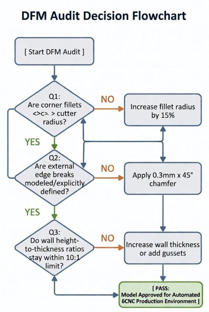
By standardizing these automated checking rules directly into your PLM (Product Lifecycle Management) software or engineering review protocols, companies can systematically design out defects before raw material is ever loaded into a machine fixture.
Download the Complete Resource
For a comprehensive, step-by-step breakdown of edge-break protocols, machinable geometric limits, and specific alloy behavior metrics, engineers can reference the complete digital 6CNC DFM Checklist. This downloadable asset serves as a real-world baseline guide, helping design offices audit their CAD files for automated in-machine finishing compliance, ensuring lower production costs and faster lead times on every order.
Conclusion
Manual deburring is an unnecessary tax on precision manufacturing that can be systematically engineered out of existence. By ensuring that pocket fillets are sized appropriately for standard cutters, enforcing rigid $L/D$ limits, replacing ambiguous drawing notes with standardized edge-break dimensions, and isolating ultra-precision tolerances only where functionally mandatory, designers can achieve a true touchless manufacturing flow. Designing for automated, in-machine finishing represents the ultimate path to scalable, high-margin precision component procurement.

![Comparison of Operating Principles: This figure illustrates a microscopic comparison of the surface waviness and residual scallop height generated by a face milling cutter and a ball-nose cutter under different stepover and step-down settings. [Figure 4-1]](https://6-cnc.com/wp-content/uploads/2026/06/image-2-300x199.png)