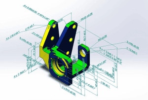

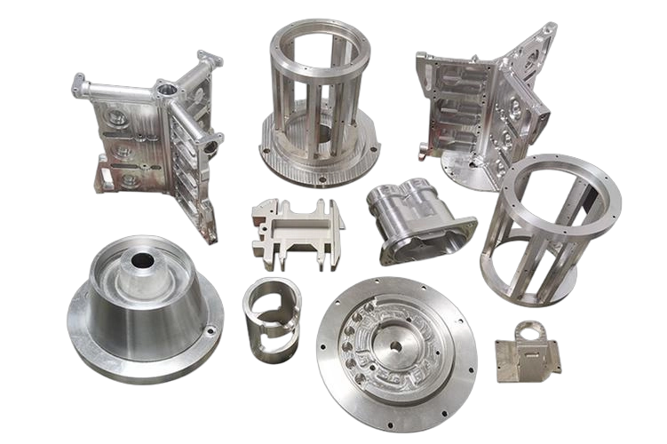
A drawing that says ±0.01 mm on every dimension usually tells us one thing: the part was designed before anyone priced it. That single decision can turn a simple milled component into a slow, expensive, high-risk job. If you want to know how to specify CNC tolerances without creating unnecessary cost or delays, start with function, not with a blanket number.
Most tolerance problems are not caused by asking for high precision. They come from asking for precision in the wrong places. A bearing bore, sealing face, and locating datum do not carry the same manufacturing risk as a non-critical outer profile. When all features get the same tolerance, your supplier has to machine, inspect, and sometimes fixture the entire part to the tightest requirement. You pay for that in cycle time, scrap risk, and lead time.
What CNC tolerances really control
A tolerance defines the acceptable variation from nominal size, form, or position. In CNC machining, that variation affects whether the part assembles correctly, moves as intended, seals, aligns, or survives service loads. It also affects process choice. The difference between ±0.1 mm and ±0.01 mm is not just a smaller number. It can mean different tooling, more stable fixturing, slower feeds, temperature control, extra in-process checks, and final inspection on a CMM.
For buyers and engineers, the practical question is simple: what does this feature need to do in the finished product? If a slot only provides clearance for a cable tie, a very tight width tolerance adds no value. If a dowel pin hole establishes repeatable alignment between two assemblies, the tolerance becomes critical because variation creates stack-up, rework, or field failures.
This is why we separate functional tolerances from nice-to-have tolerances. Functional requirements protect performance. Nice-to-have requirements often protect appearance or designer preference, and they can be relaxed if they do not affect fit or use.
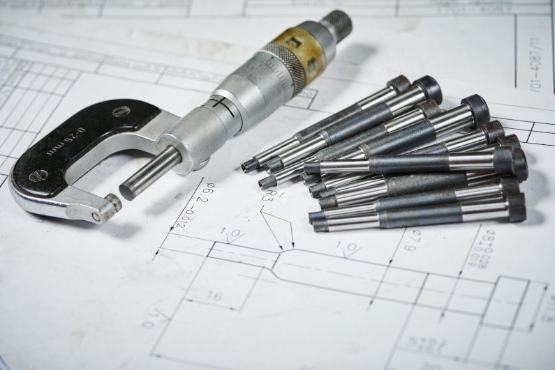
How to specify CNC tolerances based on function
The most reliable method is to classify features before you assign numbers. Start with mating features such as holes, shafts, locating faces, sealing diameters, and threaded interfaces. These usually deserve the tightest control because they affect assembly behavior directly. Next, identify secondary features such as mounting patterns, reference edges, and cosmetic profiles. These may need moderate control. Last, isolate non-critical stock-removal features where standard shop tolerances are usually enough.
A good drawing makes those priorities obvious. Instead of applying one default tolerance everywhere, define general tolerances for non-critical dimensions and then tighten only the dimensions that drive performance. This gives the machinist and quality team a clear map of where to focus process capability.
For many machined parts, a general tolerance around ±0.1 mm to ±0.05 mm is workable for non-critical features, depending on geometry, material, and size. Tighter requirements such as ±0.02 mm or ±0.01 mm should be reserved for selected features. Ultra-tight requirements down to ±0.005 mm or even ±0.002 mm are possible, but only when geometry, material stability, machine capability, and inspection method all support them. At that level, you are not buying ordinary machining. You are buying a controlled process.
The cost curve gets steep fast
Tolerance is one of the biggest cost drivers in custom machining because it compounds across the whole job. Tight dimensions increase setup time. They limit tool wear allowance. They often force additional finishing passes. Inspection also becomes slower because the measuring method must match the tolerance band.
A common mistake is treating tolerance as free if the feature looks simple. A 20 mm bore with ±0.01 mm may require boring, reaming, or grinding depending on material and depth. A flatness callout on a large aluminum plate may look harmless, but residual stress from machining can move the part after unclamping. That can require sequence changes, stress relief, or extra stock allowance for finish passes.
We regularly see drawings where relaxing one non-functional dimension from ±0.01 mm to ±0.05 mm cuts machining time significantly with no effect on assembly. That is why DFM review matters. The best tolerance is not the tightest one you can print. It is the loosest one that still guarantees performance.
Use GD&T when location matters more than size
Many tolerance issues come from relying only on plus-minus dimensions. Size tolerance alone does not fully control where a feature sits relative to the rest of the part. If hole position matters, use GD&T to define that requirement from clear datums. Position, flatness, perpendicularity, concentricity, and profile callouts often communicate design intent better than stacking multiple linear dimensions.
This matters in multi-feature parts. Think about a motor mounting plate with several bolt holes, a pilot bore, and a machined face. The pilot bore may locate the motor. The bolt holes may only clamp it. If you tighten every hole diameter and every edge dimension equally, you may still fail assembly because the hole pattern shifts relative to the pilot. A position tolerance tied to datums solves the real problem directly.
GD&T also helps reduce unnecessary precision. Sometimes a feature can vary in size more than you first assumed, as long as its true position remains controlled. That gives manufacturing more flexibility without reducing function.
Material and process change what is realistic
The same tolerance does not carry the same difficulty across all materials and methods. Aluminum usually machines predictably, but thin-wall parts can move after material removal. Stainless steel can generate more heat and tool wear. Plastics present their own challenge because they expand more with temperature and may deform under clamping. Hardened materials may require grinding or EDM for very tight control.
Part geometry matters just as much. Deep pockets, long slender shafts, thin ribs, and large unsupported surfaces all reduce achievable stability. Five-axis machining can improve access and reduce re-fixturing error on complex parts, but it does not erase geometric limitations. Turning can hold excellent concentricity on rotational parts, yet interrupted cuts or long overhangs still affect consistency.
That is why realistic tolerance specification always depends on the full context: material, feature type, part size, wall thickness, process route, quantity, and inspection method.
How to call out tolerances clearly on drawings
The drawing should answer three questions without guesswork: what matters, how much variation is allowed, and how that variation relates to the rest of the part. Clear datum structure is essential. So is a sensible title block general tolerance. Critical features should be flagged by explicit dimensions or GD&T callouts, not buried in notes.
Avoid conflicting information. If your title block says one general tolerance but a note elsewhere implies another standard, the shop has to stop and clarify. That delays quoting and production. The same problem happens when a 3D model, 2D drawing, and inspection sheet do not match.
Surface finish should also be specified only where it affects function. A sealing land, sliding contact face, or optical interface may need a defined Ra value. A hidden non-contact wall usually does not. Surface finish and tolerance often interact, because tighter finish may require different tooling or secondary processing.
When to ask your supplier before finalizing the print
If you are working on a prototype, a first article, or a low-volume custom assembly, tolerance decisions are often still flexible. That is the right time to ask for manufacturability feedback. A good machining partner can tell you which features are routine, which ones are sensitive, and where a small design change will improve consistency.
For example, adding a relief, increasing wall thickness, shortening a thread depth, or changing a blind feature to a through feature can improve control without affecting the product. On mating parts, assigning one part as the precision master and loosening the companion part often lowers total cost. On assemblies, tolerance stack-up analysis may show that one critical datum needs improvement while several other dimensions can open up.
At 6 CNC, we see this most often in prototype and small-batch programs. Teams move fast, then discover that a few inherited drawing assumptions are driving most of the cost. A short DFM review usually identifies where standard machining is enough and where precision machining should be concentrated.
The practical rule: tolerance should earn its place
If a tighter number does not improve fit, function, safety, compliance, or repeatability, it probably does not belong on the drawing. That sounds simple, but it changes how you communicate design intent. Instead of asking for maximum precision everywhere, you create a controlled risk profile for the part.
That approach gives you better quotes, fewer technical questions, and more predictable delivery. It also improves quality because the machine shop knows exactly which features must be protected through machining and inspection.
When you specify tolerances, think like the final assembly, not like the CAD model. The parts that ship on time and fit the first time are usually the ones where every tight tolerance has a clear job to do.