A part can look simple on the screen and still become expensive, late, or impossible to inspect once tolerances are applied. We see this often when a drawing carries tight limits across every feature, even though only a few dimensions matter to fit, sealing, motion, or alignment. A solid machined part tolerance guide helps you avoid that trap and specify only what the part actually needs.
For engineering teams and buyers, tolerances are not just a print detail. They directly affect machining time, inspection method, scrap rate, lead time, and supplier choice. The right tolerance strategy protects function without turning a straightforward component into a high-risk job.
What tolerance really controls
Tolerance defines how much variation a feature can have and still be accepted. That sounds basic, but the commercial impact is where projects go right or wrong. A bore tolerance may determine whether a bearing seats correctly. A flatness callout may control sealing performance. A positional tolerance may decide if an assembly goes together smoothly on the line or fails during final build.
The problem starts when all dimensions receive the same level of control. If your drawing effectively says every surface matters equally, your supplier has to machine and inspect as if every surface is critical. That usually means more setups, slower feeds, additional fixturing, tighter process control, and more measurement time. Cost rises quickly. Lead time usually follows.
In practice, most parts have only a handful of truly critical features. Those are the dimensions that should carry the tightest limits. The rest should be opened up to what the process can hold reliably.
A practical machined part tolerance guide for real projects
Start with function, not habit. Ask what each feature actually does in the finished product. If a diameter locates a shaft, its size and roundness may matter. If an outside profile has only cosmetic value and no mating role, it often does not need the same control.
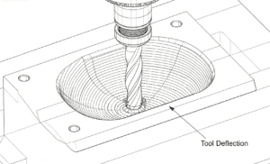
Next, consider the manufacturing route. CNC milling, turning, grinding, and 5-axis machining do not deliver the same tolerance capability at the same cost. A shop may hold ±0.01 mm on a milled feature with stable material, short tool stick-out, and good access. Push that to ±0.005 mm and the process window narrows. Tool wear matters more. Temperature matters more. Inspection becomes more demanding. If you require ±0.002 mm, the feature often moves into a different class of manufacturing and metrology altogether.
Material also changes the answer. Aluminum machines differently from stainless steel. Plastics add their own challenges because they can move during machining and after release from the fixture. Thin-wall geometry behaves differently from a compact steel block. The same numerical tolerance can be routine on one part and risky on another.
This is why we recommend assigning tolerances by feature importance. Critical features should reflect assembly and performance requirements. Secondary features should reflect practical machining capability. Non-critical features should use a general tolerance unless there is a clear reason to tighten them.
When tight tolerances are justified
Tight tolerances make sense when the feature directly affects performance, safety, or compliance. Common examples include bearing fits, sealing surfaces, valve components, precision alignment features, and optical or sensor mounting interfaces. In these cases, the cost of poor control is usually much higher than the cost of tighter machining.
They also make sense when variation stacks across an assembly. A single bracket hole may seem forgiving, but a pattern of several holes across multiple mating parts can create a serious fit problem if each dimension floats too far. Tolerance stack-up should guide where control is needed.
There is another case buyers sometimes miss. Inspection or regulatory requirements may force tighter controls than function alone suggests. Aerospace, medical, and high-end automation projects often need traceable, repeatable results, not just parts that appear to fit.
That said, tighter is not always safer. An unrealistic tolerance can increase scrap without improving the product. If the process struggles to hold the number consistently, you may receive late deliveries, high unit prices, or variation hidden by selective inspection. Good tolerancing should improve reliability, not create artificial precision.
What drives tolerance cost
Most price jumps come from process complexity, not from the number typed on the drawing. A tighter tolerance often changes how the part is made. The machinist may need roughing and finishing passes instead of one efficient operation. The part may need to rest between operations to stabilize. A grinding step may replace milling. A simple vise setup may turn into custom workholding.
Inspection cost can rise just as fast. Holding ±0.05 mm may be verified with standard tools in many cases. Holding far tighter geometric relationships may require a CMM, special gauges, temperature-controlled inspection, or repeated in-process checks. That adds labor and scheduling pressure.
Feature accessibility matters too. A tight tolerance on an open external diameter is one thing. The same tolerance deep inside a pocket, on a thin wall, or across a long unsupported span is much harder. Geometry often matters more than the tolerance value itself.
If you are buying prototypes or low-volume parts, this becomes even more important. There is less volume to absorb setup and inspection time. A drawing with blanket tight tolerances can make a prototype cost feel like a production component.
How to specify tolerances without creating delays
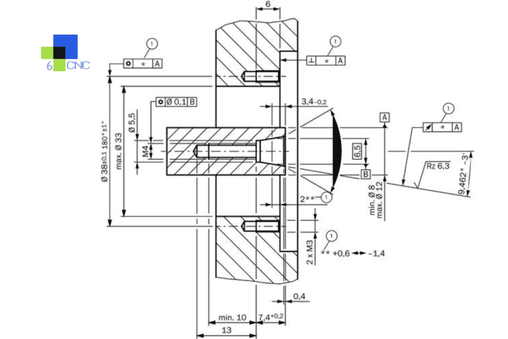
The best drawings separate critical from general requirements. Use clear datums where location and orientation matter. Apply geometric tolerances only when they solve a real functional problem. Keep title-block tolerances reasonable for dimensions that are not individually called out.
Fit classes help when mating parts are involved. If a hole and shaft relationship matters, define the fit intent instead of relying on two isolated size tolerances that may not work together. Surface finish should also be specified only where it affects sealing, wear, bonding, or appearance.
You should also align the tolerance with the quantity and project stage. Early prototypes often need enough precision to validate fit and function, not full production-level control on every detail. Once the design stabilizes, you can tighten the features tied to final performance and process capability.
A quick supplier review before release can prevent a lot of churn. We often find that one drawing note or one overlooked datum scheme is driving unnecessary cost. Small changes at that stage are much cheaper than remaking parts after inspection failure.
Common drawing mistakes this machined part tolerance guide should help you avoid
One common mistake is over-tolerancing by default. Engineers sometimes copy a previous print or apply a company standard that is far tighter than the current part requires. The result is a part that looks well controlled on paper but offers no real product benefit.
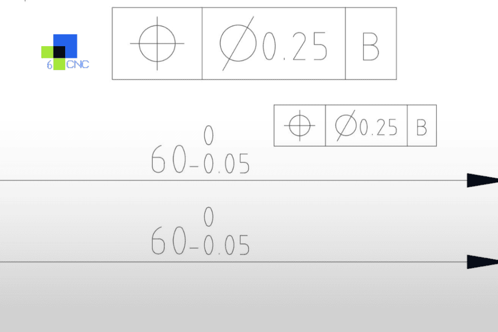
Another mistake is mixing loose size tolerances with undefined geometric relationships. A feature may be the right size and still be in the wrong place. If location matters, positional control tied to meaningful datums is usually more useful than shrinking every linear dimension.
We also see conflicting requirements. A drawing may call for a very fine surface finish on an area that will later be coated, blasted, or hidden. Or it may demand a tolerance that is tighter than the mating part can even use. These conflicts create avoidable questions during quotation and production review.
Finally, inspection must be considered from the start. If a feature cannot be measured reliably, controlling it becomes difficult in practice. Tolerance and inspection should always be thought of together.
A simple way to make better tolerance decisions
Treat tolerances as a risk management tool. Ask four questions for every critical feature. What function does it control? What happens if it drifts? What process can hold it consistently in the chosen material and geometry? How will it be verified?
That approach gives both engineers and sourcing teams a common language. Engineering protects function. Procurement protects schedule and budget. Manufacturing gets a drawing that can be executed without guesswork.
For custom CNC parts, especially in low volumes, the best results come from early alignment between design intent and process capability. At 6 CNC, that usually means reviewing the CAD model or print before production, flagging features that are unnecessarily tight, and confirming where precision truly matters. That is often the difference between a smooth build and a string of avoidable revisions.
If you are working on a new part, the smartest tolerance is not the tightest one. It is the one that gives you the performance you need, with a process your supplier can repeat confidently and inspect without ambiguity.

![Comparison of Operating Principles: This figure illustrates a microscopic comparison of the surface waviness and residual scallop height generated by a face milling cutter and a ball-nose cutter under different stepover and step-down settings. [Figure 4-1]](https://6-cnc.com/wp-content/uploads/2026/06/image-2-300x199.png)