
A part can look perfect in CAD and still fail the first manufacturing review. We see that gap often, especially when teams move fast from concept to prototype and assume the machine will solve every geometry problem. Most top CNC design mistakes are not dramatic errors. They are small design choices that quietly add cost, extend lead time, or make stable production harder than it needs to be.
For engineering teams and buyers, that matters because CNC problems rarely stay in the machine shop. They show up later as quote revisions, extra setups, scrapped parts, inspection failures, and delayed builds. Good design for machining is not about making a part simpler at any cost. It is about making it manufacturable without giving away functional performance.
Why top CNC design mistakes become expensive fast
The biggest issue is not usually raw machining time. It is process complexity. A part with deep narrow pockets, tight internal corners, and unnecessary ultra-tight tolerances may require special tools, more setups, slower feeds, and higher inspection effort. That affects quote price, but it also affects process stability.
A prototype can sometimes be forced through with enough care. Low-volume production is less forgiving. If your part depends on fragile tools, difficult workholding, or repeated manual intervention, variation increases. That is when an acceptable one-off component turns into a purchasing problem.
1. Calling out tight tolerances everywhere
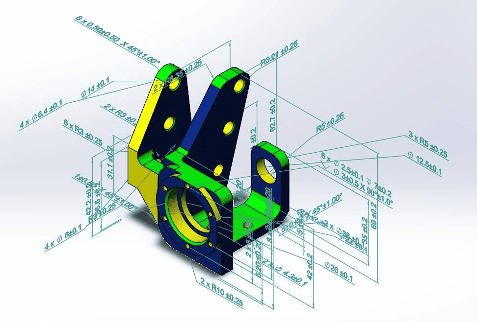
This is the most common and most expensive mistake. Many drawings apply very tight tolerances across all dimensions, even when only a few features actually affect fit, sealing, alignment, or motion. A tolerance of ±0.002 mm may be achievable on specific critical features, but using it broadly is not a neutral choice. It increases machine time, tool wear, inspection time, and scrap risk.
The better approach is functional tolerancing. Keep tight control where performance depends on it, and relax everything else to standard machinable ranges. If two holes must locate a bearing housing, control those. If an outer non-mating face only needs cosmetic consistency, give it more room. You lower cost and improve yield without changing how the assembly works.
What to do instead
Tie each critical tolerance to a functional need. If no assembly, motion, or sealing requirement depends on the number, question it. Your machinist and your quality team will both thank you.
2. Designing internal corners that standard tools cannot make
End mills are round. Internal corners are not. Yet many parts arrive with sharp internal corners inside pockets and slots, especially when models come from molded or sheet metal concepts. To machine those features exactly, a shop may need very small cutters, EDM, or design changes after review.
Small tools create two immediate problems. They remove material slowly, and they break more easily. Deep sharp corners make that even worse because the tool has less rigidity. A seemingly minor corner detail can therefore drive a major cost increase.
Use internal radii that match realistic tool sizes. If a mating component needs clearance, add dog-bone or T-bone relief where appropriate. That small design change often turns a difficult feature into a routine operation.
3. Making pockets too deep for their width
Deep pockets and slots are classic machining traps. Once depth grows too far relative to tool diameter, tool deflection becomes a real issue. Surface finish degrades, dimensions wander, and cycle time rises because the machine must cut more carefully.
A common rule of thumb is to avoid pocket depths greater than about 4 times the tool diameter unless there is a strong reason. Deeper features are possible, but they should be treated as exceptions, not defaults. If the design truly needs depth, widening the pocket or changing the part orientation may help.
This is one of those it-depends cases. Aluminum allows more flexibility than hardened steel. A one-off prototype may tolerate a slower process. A repeat production part usually should not depend on a marginal toolpath.
4. Using thread specs that are difficult to machine and easy to damage
Threads look simple on a drawing. In production, they can become failure points. Very small threads, unnecessary thread depth, and thread placement near thin edges all increase risk. Threads deeper than needed add cycle time with little functional benefit because most assemblies do not gain strength from excessive engagement.
For metal parts, a practical target is often thread engagement around 1 to 1.5 times the fastener diameter, depending on material and load. More than that may only add machining effort. Blind holes also need proper bottom clearance so the tap or thread mill can run cleanly.
If the part will be assembled often, think about wear. In softer materials such as aluminum, threaded inserts may make more sense than direct threads. That decision can improve service life and reduce field failures.
5. Forgetting how the part will be held during machining
A CAD model does not need clamps. A real part does. Workholding is where many elegant designs become awkward jobs. Thin walls, irregular shapes, and minimal flat reference surfaces make the part harder to secure. Once clamping becomes unstable, dimensional control becomes unstable too.
We often advise customers to include at least one or two reliable datum surfaces early in the design. Those surfaces help during machining and inspection. If a part has to be machined from several sides, think about the setup sequence before freezing the geometry. A feature that blocks tool access in setup three can force a full redesign of setup one.
Design with machining sequence in mind
Ask a simple question: what surface gets made first, and what surface references the rest? That question catches many manufacturability issues before they affect schedule.
6. Leaving walls too thin
Thin walls save weight, but they also move. During machining, cutting forces and heat can deform slender features. After machining, residual stress can release and shift the part further. That is why a wall that measures correctly during roughing may move after finishing.
Material matters here. Plastics and soft aluminum alloys are more prone to deformation than tougher metals. Geometry matters too. A tall unsupported wall behaves very differently from a short rib with nearby support.
As a starting point, metal walls under about 0.8 mm and plastic walls under about 1.5 mm deserve extra review. Those numbers are not absolute limits, but they are useful warning signs. If you need very thin features, discuss machining strategy and inspection method early.
7. Ignoring standard stock sizes
Custom geometry is fine. Custom raw material dimensions for no reason are not. When a part barely exceeds a common stock size, cost can jump because the shop must source larger material, remove more excess, or use a less efficient starting form.
This mistake is easy to miss during design because the CAD model does not show purchasing impact. A few extra millimeters on overall size may look harmless but can affect availability, waste, and lead time. For low-volume work, those effects are often visible immediately in the quote.
If function allows, align your design with common bar, plate, or billet sizes. You may reduce both material cost and machining time.
8. Overcomplicating surface finish requirements
Not every face needs a premium finish. Drawings that call for low roughness values across the entire part often create unnecessary secondary operations. Fine finish requirements can force slower cutting parameters, additional passes, grinding, polishing, or more careful handling.
Surface finish should match function. Sealing faces, sliding surfaces, optical interfaces, and visible cosmetic faces may need tighter control. Internal non-contact surfaces usually do not. The same logic applies to edge break requirements and cosmetic standards. Be specific where it matters instead of broad everywhere.
9. Mixing too many difficult features into one part
A single part can include five-axis contours, deep cavities, micro threads, thin ribs, and tight positional tolerances. That does not always mean the design is wrong. Sometimes the application justifies it. But complexity stacks risk.
Each advanced feature may be individually machinable. Combined, they can create a narrow process window. The quote gets higher, setup planning gets longer, and quality control gets more demanding. If the project is still in development, consider whether one complex part should become two simpler parts in assembly. You may gain better manufacturability, easier maintenance, and lower total cost.
10. Sending incomplete drawings or unclear revision data
This is technically a documentation mistake, but it causes real CNC problems. Missing tolerances, inconsistent units, undefined datums, and conflicting CAD versus drawing revisions all create manufacturing risk. Shops then have two bad choices: pause for clarification or make assumptions.
Neither helps your schedule. The cleanest projects are not always the simplest parts. They are the parts with complete technical definition. A controlled drawing package, clear critical-to-quality notes, and aligned revision history prevent expensive back-and-forth.
How to catch CNC design mistakes before release
The most effective fix is early DFM review. That means checking the part before purchase order release, not after first article failure. Look at tolerance stack-ups, tool access, wall thickness, workholding, material availability, and inspection method as one system. CNC success depends on all of them.
For prototype teams, speed matters. For OEMs and purchasing teams, repeatability matters just as much. The smart path is to design for both. At 6 CNC, we have seen small changes in corner radius, tolerance scope, or stock selection cut machining difficulty significantly without changing part function.
If you want better parts, ask a harder question than can this be machined. Ask whether it can be machined consistently, inspected reliably, and delivered on your schedule without hidden cost. That is where strong CNC design starts.