
All Custom Parts / Brackets
6CNC · Structural components
Custom CNC Machined
Brackets
6CNC manufactures custom CNC machined brackets for automotive mounting, automation fixtures, and industrial equipment. We review your drawing for hole position, reference surfaces, machining access, and assembly tolerance relationships.
Hole position · Reference faces · Mounting fit
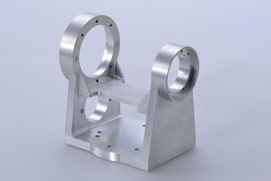
Manufactured to your drawing · Prototypes and production runs
Bracket Geometries and Mounting Interfaces
Identify the shape and interfaces closest to your drawing. Hole patterns, mating surfaces and load paths determine the machining and inspection plan.
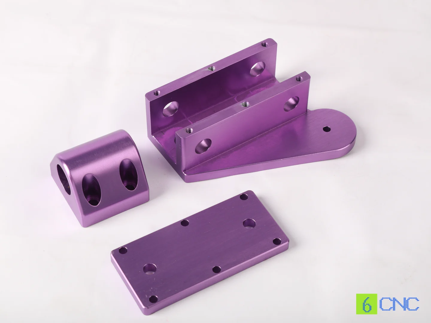
Ribbed angle brackets
An angled mounting body with a reinforcing web. Define the relationship between the base, upright face and hole pattern; pocketing must leave the required wall and rib thickness.
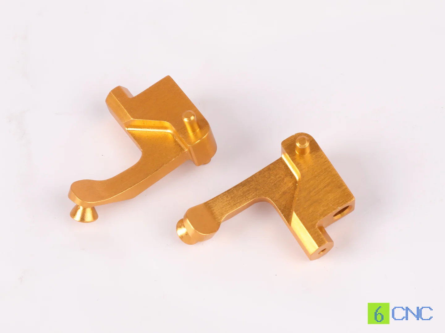
Forked mounting brackets
Fork-shaped mounting pieces with separated arms and fastening features. Specify arm spacing, mating clearances and the relationship of the mounting holes to the base.
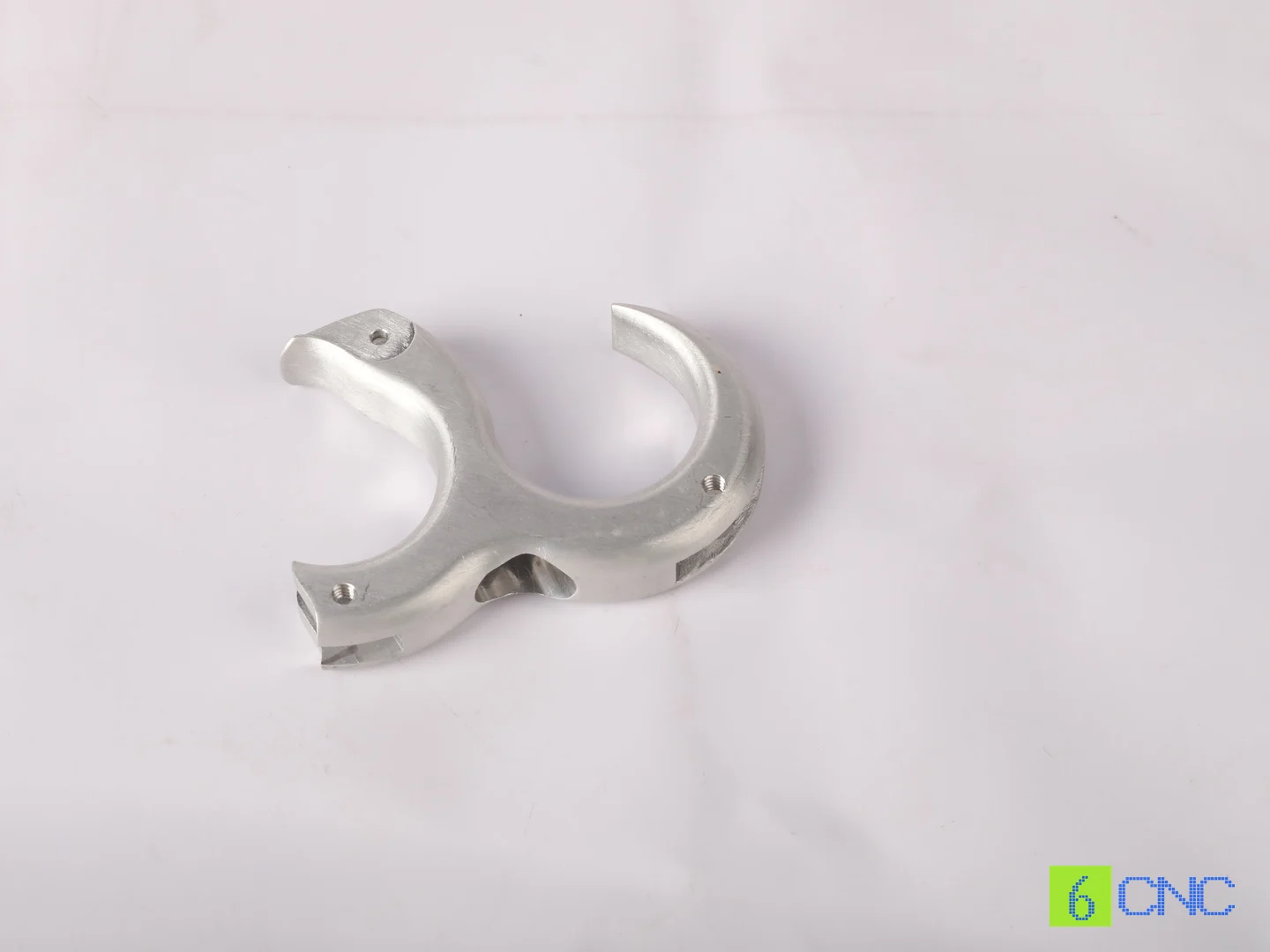
Curved clamp brackets
Curved supports with a circular seating profile. Define the mating diameter, split or assembly condition and the locating faces that establish the installed position.
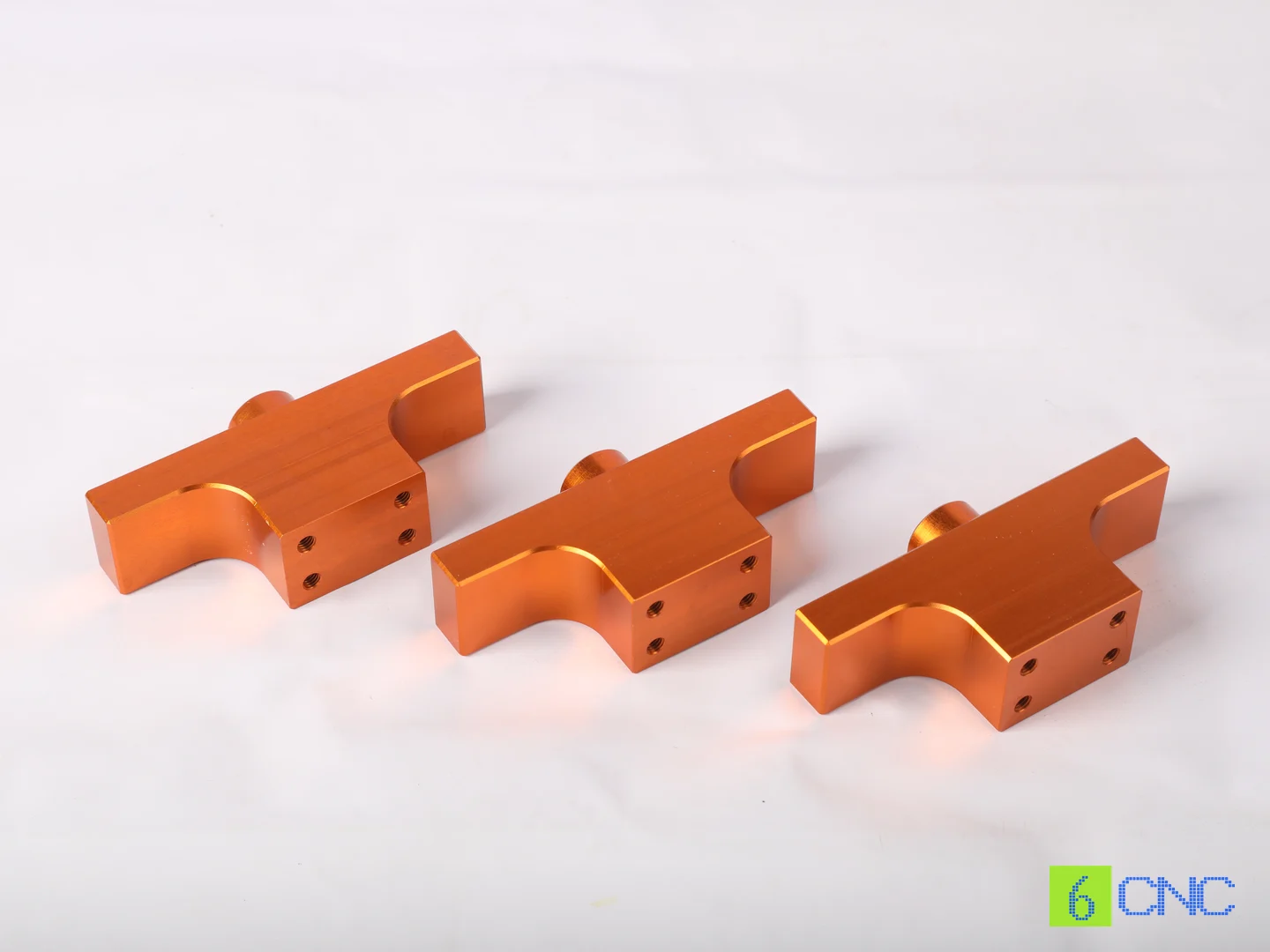
Saddle mounting brackets
Stepped mounting bodies with curved seats and side features. Specify seat geometry, mounting-hole locations and access for fasteners or adjoining components.
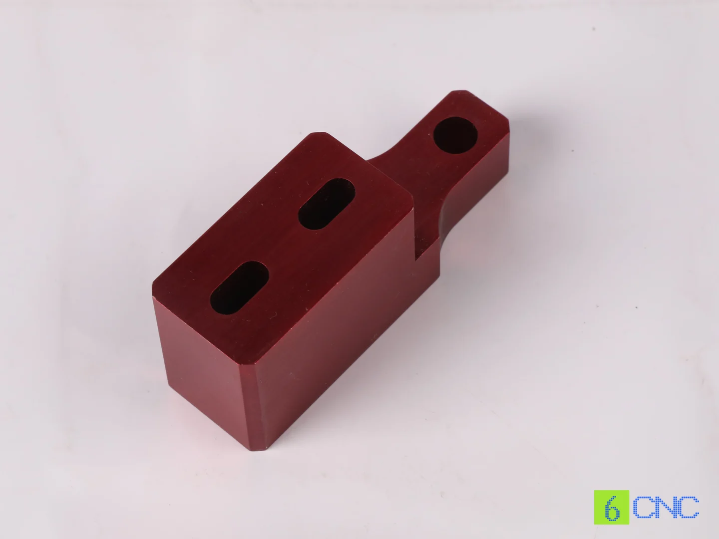
Slotted mounting blocks
Mounting blocks with elongated slots and a raised end feature. Specify adjustment travel, slot width, edge distances and the faces that locate the assembly.
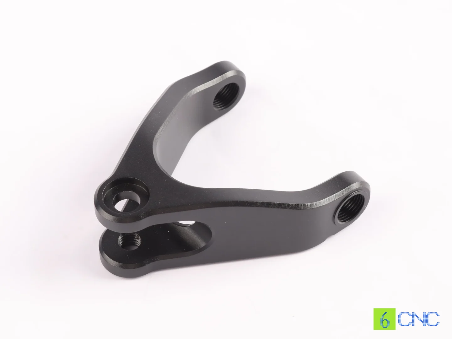
Forked linkage supports
Three-dimensional arms with circular end interfaces. Control bore relationships and clearance between the arms; multi-face access may influence the setup strategy.
Features That Determine Bracket Fit
Use functional requirements to decide where precision is needed. The complete datum scheme matters more than applying one tight tolerance to every surface.
Mounting faces and perpendicularity
Identify the seating plane and upright reference face. Flatness and perpendicularity should follow the assembly requirement, with measurement referenced to the same datums.
Hole spacing and locating pins
Distinguish clearance holes from locating holes. Specify hole position relative to datums and identify any dowel-hole fit; bolt clearance alone does not establish precise location.
Slots, counterbores and threads
State the slot width and travel, fastener-head clearance, thread size and effective depth. Include access for tightening and any inserts required by the design.
Ribs, pockets and tool access
Ribs can retain support while pockets remove material. Specify minimum wall thickness and practical internal radii; deep narrow cavities can require longer, less rigid tools.
Thin walls and released-part geometry
Thin sections can distort during clamping and machining. Review support, material removal sequence and inspection after release from the fixture.
Dimensions after finishing
Identify critical bores, threads and seating faces to mask or finish-machine. Coating thickness and cosmetic surfaces need to be planned before final inspection.
CNC Machining or Bent Sheet Metal?
Choose the manufacturing route around the interfaces, stiffness requirement, quantity and total cost. A bracket does not need to be milled from solid simply because it is custom.
| Design requirement | CNC-machined bracket | Bent sheet-metal bracket |
|---|---|---|
| Thick sections, pockets or integral ribs | Can combine several features in one machined body. | May need welded reinforcements or additional parts. |
| Simple thin walls with mainly uniform thickness | Material removal can be unnecessary. | Often a practical route when bend geometry is suitable. |
| Precise bores and related mounting faces | Datum-based machining can control these relationships. | May require machining after bending or assembly. |
| Design changes and order quantity | Programming and fixtures can adapt to prototypes and small batches. | Laser cutting and bending can also suit low quantities; dedicated tooling depends on the design. |
Provide the approved load and stiffness requirements where relevant. Material grade, bend allowances, machining sequence and any testing must be assessed for the actual design.
Capability reference
Brackets Machining Specifications
Use these published 6CNC reference ranges to begin your enquiry. The quotation confirms what applies to your actual part.
| Item | Published scope & project review |
|---|---|
| Materials | Aluminum, stainless steel, carbon steel, and brass. |
| Published size reference | Custom sizes, typically up to 800 mm; actual envelope and feasibility require drawing review. |
| Tolerance reference | ±0.01–±0.05 mm, depending on feature, material, geometry, and inspection method. |
| Quantity | 1–600 pieces. |
| Processes | CNC milling, turning, and multi-axis machining. |
| Surface treatments | Anodizing, powder coating, plating, and polishing, subject to material and functional requirements. |
Source: 6CNC’s existing brackets service information. Ranges are not simultaneous limits or default acceptance criteria. Material, size, geometry, finish, inspection, and order scope determine the confirmed capability and schedule.
Bracket Materials and Finished Interfaces
Select material from the approved mechanical design, then specify the finish and functional dimensions together.
Aluminum brackets
6061 can be considered for general machined mounting parts; 7075 may be selected where the design calls for higher strength. Anodizing requires allowance or masking at critical fits and electrical contact faces.
Stainless-steel brackets
Grades such as 304 or 316 may suit corrosion-related requirements. Review grade, condition, machining access and the specified passivation or surface treatment.
Carbon- or alloy-steel supports
Often considered for stiffness, wear or load-related requirements. State the exact grade and heat treatment; coating, plating or other corrosion protection must match the application.
Finish and mating-part compatibility
Define visible surfaces, color, contact faces and masking. Powder coating is not a default finish for close fits; final dimensions should be specified in the delivered condition.
Manufactured by 6CNC
Inspection Follows the Features That Matter
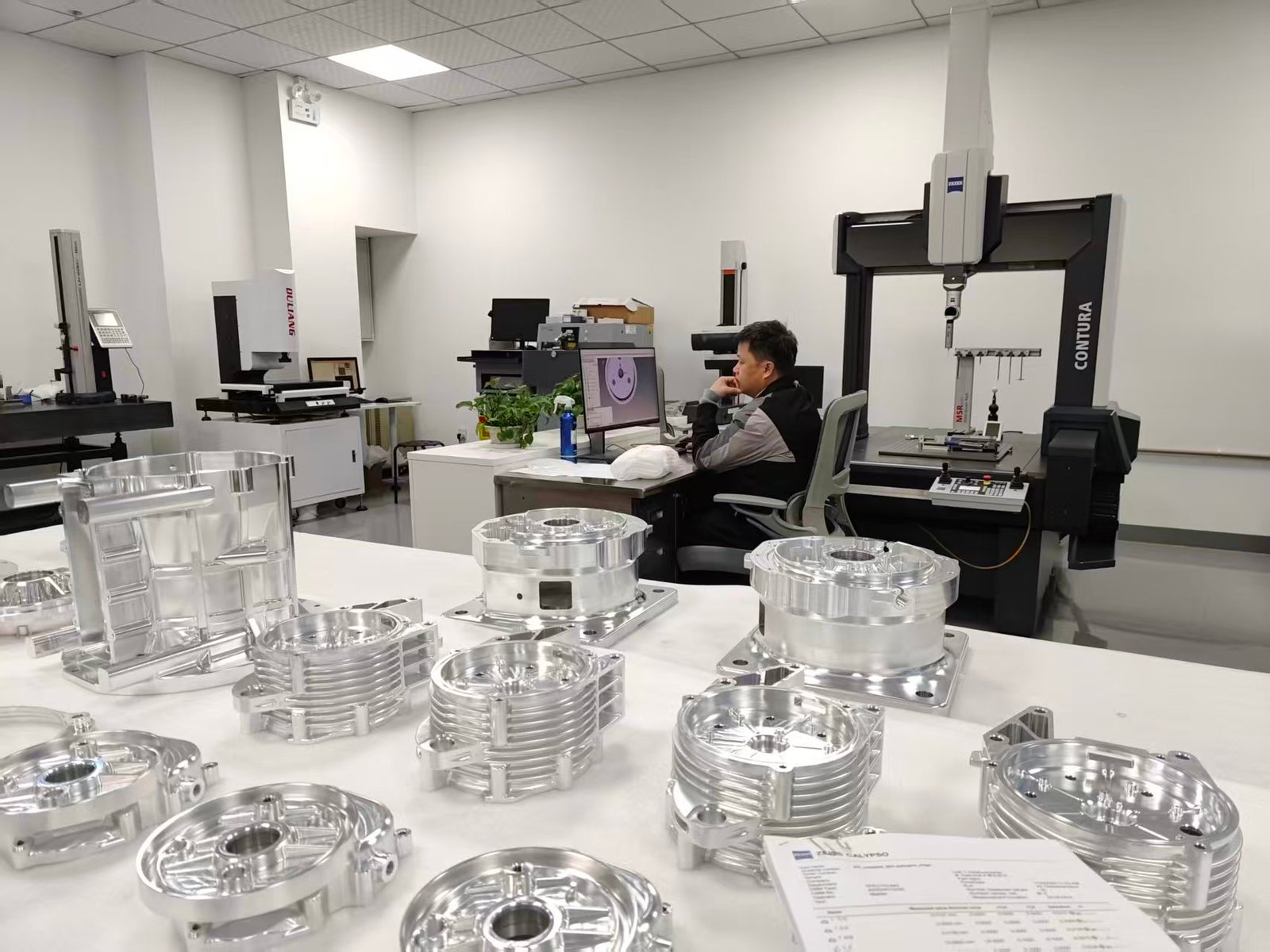
Check the features that locate the bracket in the assembly: reference surfaces, hole position, slot size, threads, and specified dimensions after finishing. Agree the inspection report and acceptance criteria before production.
01
Review the drawing
Confirm the material, geometry, critical features, quantity, and acceptance requirements.
02
Agree the route
Plan machining, workholding, any outside treatments, and inspection checkpoints.
03
Machine & finish
Produce the agreed drawing revision and coordinate the specified finishing sequence.
04
Inspect & prepare
Complete the agreed checks, documentation, and packaging for the order.
Before you enquire
Brackets Machining FAQ
Can you manufacture a bracket from my CAD files?
Yes. Supply a 3D model and controlled drawing with material, critical dimensions, finish, quantity, and inspection requirements.
Do you validate the bracket’s load capacity?
6CNC manufactures to the supplied design. Provide the approved structural requirements and any specified testing; machining a bracket does not itself certify its load capacity.
How should I specify mating holes and slots?
Use a clear datum scheme and identify the features that control assembly. Include the mating-part information where it affects fit or measurement.
Can you machine L-shaped, forked or curved brackets?
Yes, subject to drawing review. Send the complete geometry and mating interfaces so we can assess tool access, setups, material and inspection requirements.
Should a bracket be machined or made from bent sheet metal?
Simple uniform thin-wall shapes may suit cutting and bending. Precision bores, thick sections, integral ribs or several related machined faces can favor CNC machining. Compare the complete route and quantity.
How should I specify the hole pattern?
Define functional datums and distinguish clearance, threaded and locating holes. Include position requirements, pin fits, slot travel and the mating-part information needed for inspection.
Will anodizing or coating affect the fit?
It can change delivered dimensions. Identify critical holes, threads, seating surfaces and electrical contacts, and agree on masking or post-finish machining where required.
Start your project with 6CNC
Request a Bracket Quote
Send your files and project requirements to 6CNC. Our team will review the drawing, material, machining route, finishing, inspection, and delivery needs for a project-specific quotation.
Include with your enquiry
- 3D CAD model and controlled 2D drawing
- Material grade and condition
- Critical dimensions and mating-part details
- Quantity, finish, and inspection requirements
- Delivery target and required documentation