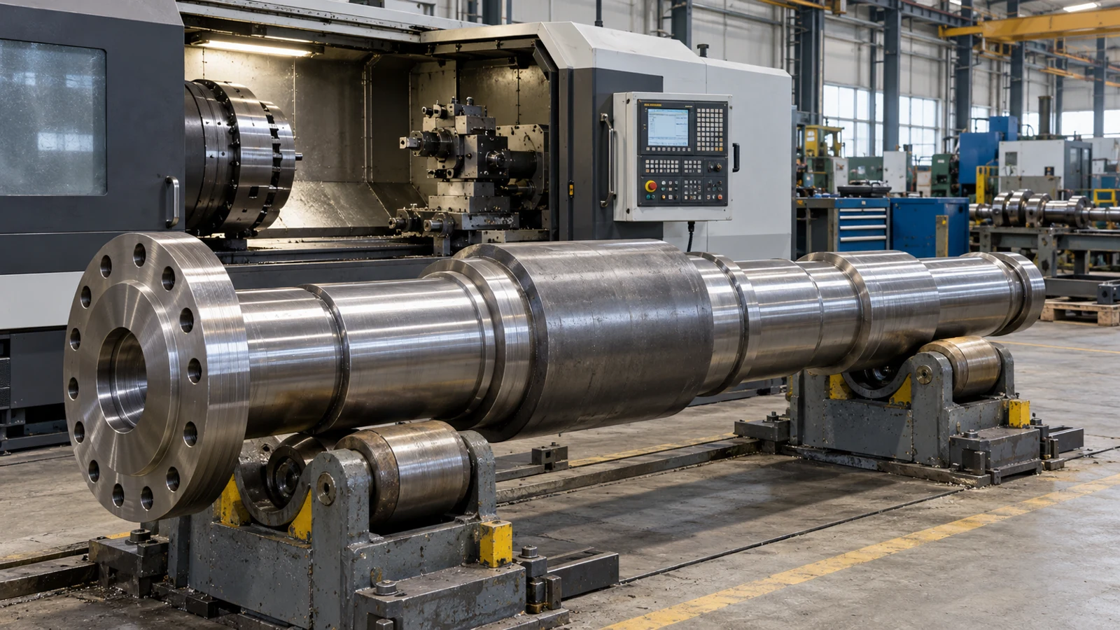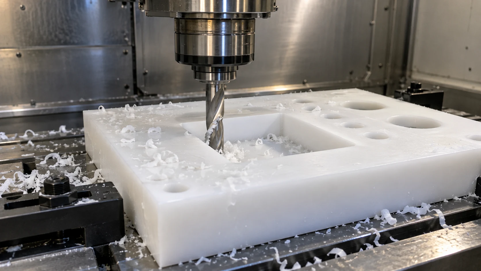
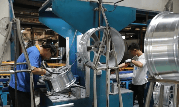
When purchasing precision machined components, a common misconception among procurement officers and junior engineers is that a state-of-the-art, multi-axis CNC machine spits out a flawless, ready-to-use part straight from the fixture. In reality, what happens after the spindle stops turning is often just as critical—and expensive—as the machining itself.
Post-processing—ranging from manual deburring and tumbling to chemical etching, bead blasting, and electrochemical polishing—is a staple in CNC manufacturing. According to comprehensive data from the National Institute of Standards and Technology (NIST), edge finishing and defect removal account for 15% to 20% of the total manufacturing cost of precision components. In high-precision verticals like aerospace and medical device manufacturing, this figure can skyrocket to 30% or more due to stringent regulatory compliance and zero-defect tolerances.
For a modern precision machine shop, post-processing represents a massive operational bottleneck. It is highly dependency-driven, labor-intensive, and prone to human error. To build a highly profitable, data-driven manufacturing pipeline, engineers must treat post-processing not as an inevitable after-thought, but as a engineering variable that can be controlled, optimized, and drastically reduced.
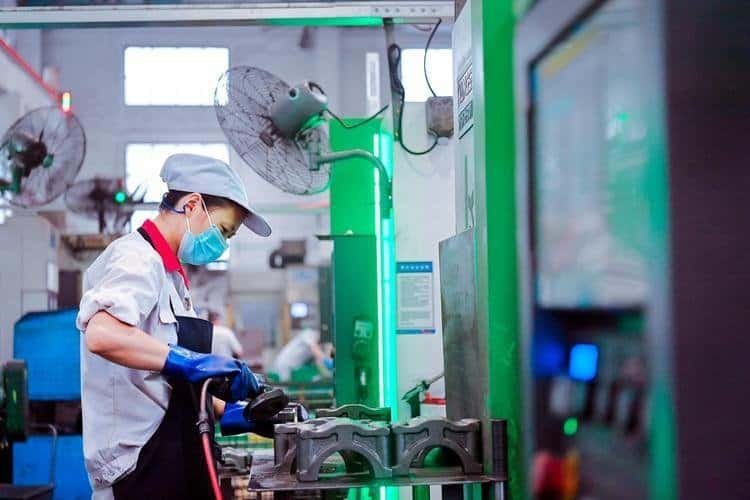
1. The Root-Cause Breakdown: The Physics and Mechanics of Burr Formation
To systematically eliminate post-processing, we must first look at the micro-mechanics of the cutting zone. Surface imperfections and burrs are not random anomalies or results of “bad luck”; they are the mathematically predictable outcomes of plastic deformation and material shearing.
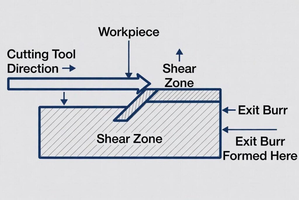
The Micro-Mechanism of Burr Formation
During a typical metal-cutting operation (whether milling, turning, or drilling), the cutting tool exerts immense compressive and shearing forces on the workpiece. As the tool moves through the material, it creates a localized shear plane.
When the tool is safely within the boundaries of the workpiece, the surrounding material provides enough backup rigidity to force the metal to fracture cleanly into a chip, which is then evacuated. However, when the cutting tool reaches an edge—such as the end of a block or the exit point of a hole—the supporting material volume drops to zero.
Instead of being sheared cleanly, the remaining thin section of metal yields under the intense cutting temperature and compressive force. It undergoes plastic deformation and rolls over the edge. According to industrial manufacturing studies by toolmaker Sandvik Coromant, burrs are classified into three primary micro-mechanical categories based on how they form:
- Poisson Burrs: Formed when the tool compresses the material downward, causing it to bulge outward sideways from the cutting path.
- Roll-Over Burrs: Formed at the end of a cut when the chip does not separate cleanly but instead rolls over the exit edge, leaving a heavy, stubborn flap of metal.
- Tear Burrs: Typically occurring in heavy-duty milling operations where the chip is literally torn from the workpiece rather than sheared, leaving a ragged, jagged boundary.
Three Primary Catalysts of Post-Processing Burden
While every cutting action creates micro-scale anomalies, the severity of the industrial post-processing workload usually boils down to three primary, interacting root causes:
A. Tool Geometry, Coating, and Micro-Wear
The sharpness of the cutting edge is the single most critical factor in controlling edge quality. A brand-new solid carbide end mill features a highly defined, micro-honed cutting edge that shears metal cleanly. As the tool undergoes flank wear and crater wear, that sharp edge rounds over.
Once the tool radius exceeds a critical threshold, it stops shearing and begins plowing the metal. Plowing increases frictional heat, forces the material into its plastic zone, and exponentially increases both the thickness and height of the exit burr. Furthermore, the lack of specialized coatings (like TiAlN for abrasive materials or DLC for aluminum) accelerates this degradation, turning a clean process into a high-burr nightmare within a few dozen cycles.
B. Material Ductility and Strain-Hardening Behavior
The mechanical properties of the chosen alloy dictate its behavior at the shear plane. Materials with high elongation at break and low thermal conductivity are notoriously difficult to machine cleanly.
For instance, when machining ductile alloys, the metal stretches significantly before fracturing, creating thick, highly adherent roll-over burrs. Compounding this issue is strain-hardening: as the tool plows through the material, the deformed metal at the edge undergoes work-hardening, making the resulting burr harder and tougher than the parent material itself. This makes subsequent manual removal incredibly difficult and destructive to finishing tools.
C. Part Geometry and the “Intersecting Feature” Pain Point
Complex geometries are the ultimate catalyst for stubborn internal defects. The primary culprit is the intersecting feature, most commonly seen in cross-holes (such as internal fluid galleries, manifold blocks, or cross-drilled shafts) and internal slots.
When a secondary drill breaks through the wall of an existing internal bore, the tool exits the material along an elliptical, multi-axis curve. The exit angle varies continuously along the contour of the intersection. Because the tool cannot maintain a consistent exit vector, it leaves a heavy, ragged internal burr inside a hidden cavity where manual deburring knives cannot easily reach.
2. CNC Material Defect Atlas & Labor Impact Analysis
To optimize finishing protocols, manufacturing engineers must understand the direct correlation between a material’s metallurgical profile and the human labor required to finish it.
Every minute an experienced technician spends under a microscope with a manual scraping tool, an orbital sander, or a dental pick is a direct drain on a workshop’s throughput. It increases lead times, inflates labor costs, and introduces human error (such as accidentally gouging a critical sealing face).
Below is an expanded, production-ready reference guide cross-referencing common industrial alloys, their defect profiles, and their quantified impact on workshop labor allocation:
| Material Grade | Metallurgical Profile | Burr Tendency Rating | Dominant Defect Profile | Labor Impact & Post-Processing Load Assessment |
|---|---|---|---|---|
| Aluminum 6061-T6 | High ductility, low hardness, excellent thermal conductivity. Generally free-machining. | Medium | Heavy entrance and exit roll-over burrs, especially when using standard general-purpose carbide tooling. | Low to Medium Load: The resulting burrs are soft and non-work-hardened. They can be removed rapidly using automated batch operations like vibratory ceramic media tumbling or automated bead blasting. Minimal manual intervention required. |
| Aluminum 7075-T6 | High zinc content, higher tensile strength, significantly more brittle than 6061. | Low | Micro-burrs; occasional small flake burrs at high exit feed rates. | Low Load: Because 7075-T6 chips fracture much more cleanly under shear, edge deformation is kept to an absolute minimum. Parts often go straight from the machine to anodizing with only a nominal chemical etch or light wash cycle. |
| Stainless Steel 316L | High chromium-nickel content, extreme toughness, high elongation, high tendency to strain-hardened. | High | Thick, razor-sharp, highly adherent exit burrs; heavy thermal scuffing; micro-tearing along thin walls. | High Load: Burrs are heavily work-hardened and cannot be removed via standard tumbling without destroying part tolerances. Requires intensive manual scraping with specialized carbide blades, high-pressure water jet deburring (up to 1000 bar), or electrochemical machining (ECM). |
| Titanium Ti-6Al-4V (Grade 5) | Extremely low thermal conductivity, high strength-to-weight ratio, high chemical reactivity with tools. | Very High | Micro-cracks along sharp corners, heavy flashing, galled surface finishes, and severe thermal discoloration. | Critical Load: Massive impact on labor. Manual finishing must be performed under magnification to prevent micro-fissures from becoming propagation points for fatigue failure. Requires automated abrasive flow machining (AFM) or extensive hand-polishing by highly paid specialists. |
| Inconel 718 | Nickel-based superalloy, extreme high-temperature strength, severe work-hardening rates. | Extreme | Massively deformed, ultra-hard roll-over burrs; severe surface tearing; micro-chatter marks. | Maximal Load: Rapidly destroys cutting edges within minutes, leading to immediate plowing. Post-processing requires specialized thermal energy method (TEM) blasting or manual diamond-honed abrasive polishing. |
3. Advanced Engineering Strategies: Eliminating Post-Processing at the CAM Stage
The most economical and scaleable post-processing strategy is a simple philosophical shift: prevent the defect from ever forming on the CNC machine. Rather than treating deburring as a downstream manual task, it must be engineered into the CAM (Computer-Aided Manufacturing) toolpath and tooling strategy.
Toolpath Optimization & Precise CAM Parameters
Data from industrial cutting research demonstrates that modifying how a milling cutter enters and exits the boundary of a part can alter the mechanical forces enough to reduce burr height by up to 70%. Engineers should implement the following specific, verifiable parameters within their CAM software (such as Mastercam, Fusion 360, or Hypermill):
1. The Radial Engagement Strategy ($a_e$)
Never program a milling toolpath where the cutter exits the part boundary at a full $100\%$ width-of-cut immersion. When a tool exits with its centerline aligned directly with the part edge, the chip thickness is at its maximum at the exit point, causing massive roll-over burrs.
Instead, maintain a radial engagement ($a_e$) of $60\%$ to $70\%$ of the cutter diameter. This ensures that as the insert or flute exits the metal, the chip thickness theoretically drops down toward zero (chip thinning effect), cleanly slicing the material off rather than pushing it over.
Incorrect (100% Engagement):
[ Cutter Centerline ] ===> Aligned with Edge ---> Maximum Exit Burr

Correct (60-70% Engagement):
[ Cutter Centerline ] ---> Offset from Edge ---> Chip Thins to Zero at Exit
2. Roll-On / Roll-Out Entry and Exit Angles
Avoid straight-line, perpendicular toolpaths when entering or exiting a face milling cut. Forcing a cutter to exit a block at a sharp $90^\circ$ angle causes a sudden unloading of cutting forces, tearing the edge.
Always program an arc-like entry and exit toolpath, ensuring the cutter exits the material at a smooth $45^\circ$ rolling angle. This gradual exit redistributes the residual cutting vectors along a wider edge area, minimizing exit deformation.
3. Strict Tool Overhang Ratios ($L/D$)
To eliminate surface chatter and rework marks—which often force operators to manually use orbital sanders to restore surface finish—adhere strictly to tool rigidity guidelines. Keep the Tool Overhang Ratio ($L/D$, Length over Diameter) below $3:1$ for standard carbide steel tooling, and never exceed $5:1$ unless utilizing specialized heavy-metal or solid tungsten-carbide shank holders. High deflection ($Y = \frac{F \cdot L^3}{3 \cdot E \cdot I}$) directly translates into microscopic edge tearing and surface waviness.
       +---+======+=========================+
       |   |      |                         |  <-- Tool Shank
       +---+======+=========================+
                  | <-- Length (L) --> |
                  |                    |
                  +-------+------------+
                  | Flutes| Diam. (D)  |
                  +-------+------------+

                  * Keep L/D ratio below 3:1 for optimal rigidity.
4. Feed Rate Retention at Corners
When a CNC machine changes direction at a sharp corner, the linear axis decelerates while the spindle RPM remains constant. This causes a dramatic drop in feed-per-tooth, resulting in the tool rubbing against the material, overheating it, and creating heavy corner flashing. Engineers must enable Corner Feed Acceleration or Adaptive Feed Control in CAM to dynamically adjust feed rates around tight radii.
Specialized Automated Tools for the Cross-Hole Pain Point
Manual scrapers cannot maintain consistency inside hidden, internal intersections. To completely automate the deburring of cross-holes and internal slots, modern machine shops must bypass manual labor by integrating specialized, spring-loaded, or multi-axis mechanical deburring tools directly into the CNC tool carousel.
A. Retractable Clamping Chamfer Tools (e.g., Heule COFA & SNAP Series)
The Heule COFA system is a prime example of an elite automated solution for cross-hole intersections. This tool features a spring-loaded, surface-guided carbide blade that sits inside a hardened steel shaft.
As the tool enters a bore, the blade cuts a clean, consistent $45^\circ$ chamfer on the front edge. Once inside the hole, the blade retracts completely into the shaft under mechanical pressure, preventing damage to the internal bore wall. Upon exiting the back side of the hole, the blade springs out again, cutting a perfect rear chamfer on the reverse cross-hole intersection in a single, continuous spindle operation. This completely eliminates the need to manually flip the part or hand-scrape hidden edges.
Heule COFA Principle:
1. Tool enters bore -> Blade cuts front chamfer.
2. Tool passes through -> Blade retracts safely into shaft.
3. Tool exits back side -> Blade springs out to cut back chamfer automatically.
B. Elliptical Contouring Tools (e.g., JW-Donegal ORBITOOL)
For highly complex, non-planar cross-hole intersections (such as a small hydraulic channel breaking into a larger cylinder at an oblique angle), standard deburring tools cannot follow the undulating three-dimensional path.
The ORBITOOL features a unique design: a polished, non-cutting hemispherical tip protecting a micro-toothed carbide cutter just behind the apex. The CAM programmer drives the tool into the center of the intersection and runs a simple circular interpolation path.
The smooth tip rides safely along the major internal bore wall, while the exposed cutting teeth engage perfectly with the raised, irregular internal burr crest. This removes the flash mechanically without modifying the critical geometric tolerance of either bore.
4. Case Studies, Industry Benchmarks, and Data Integration
To understand the real-world financial return of shifting away from post-processing manual labor, we can look at documented implementation data from high-precision manufacturing environments.
Real-World Case Study: Medical-Grade Orthopedic Implant Supplier
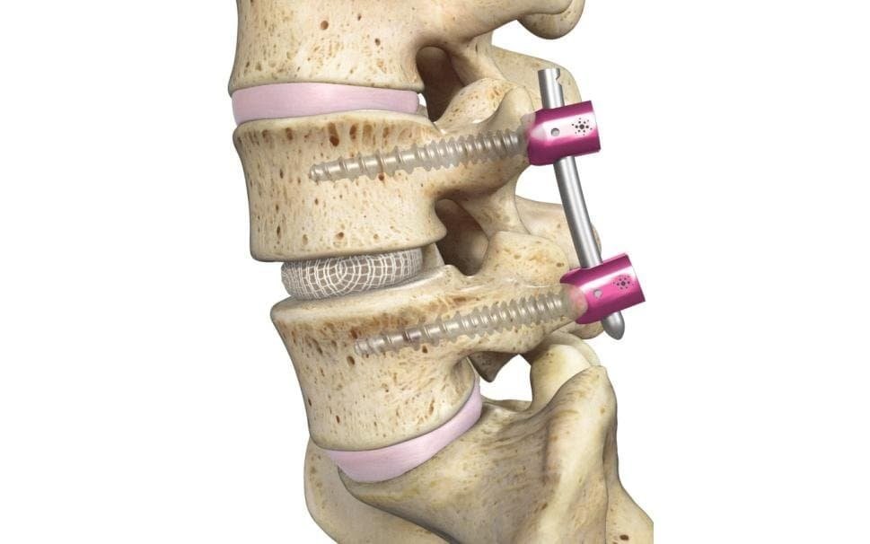
A tier-1 medical device manufacturer was producing custom bone-fixation plates and spinal cages from medical-grade Stainless Steel 316L and Ti-6Al-4V. Due to the intricate geometry of the bone-screw locking mechanics, each plate contained multiple small, intersecting threaded and unthreaded cross-holes.
- The Original Baseline Process: The parts came off the 5-axis CNC mill with significant exit burrs. Operators had to manually clean each hole using hand-held miniature scraper knives and specialized micro-abrasive rubber points under a stereo microscope. This manual process took an average of 12 minutes per part, represented a massive line bottleneck, and suffered a 4.2% scrap rate due to occasional manual tool slippage that scratched critical sealing faces.
- The Automated Solution: The engineering team overhauled the CAM program. They updated toolpaths to maintain a strict $65\%$ radial engagement on all exit faces and integrated a Heule SNAP micro-tool into the tool changer for automated back-side hole chamfering. Tool change intervals were rigidly locked into the ERP system based on a strict wear schedule to prevent tools from ever entering the “plowing” zone.
- The Quantifiable Results: The automated, in-machine finishing strategy reduced the downstream post-processing time from 12 minutes down to just 7 minutes per part—a massive $41.6\%$ reduction in cycle time. Furthermore, because human variability was completely eliminated from the deburring loop, the component scrap rate dropped from 4.2% to absolute zero (0.0%), saving tens of thousands of dollars in raw titanium inventory per quarter.
[ Manual Process ]  =========> 12 Minutes/Part (4.2% Scrap Rate)
[ Automated CAM ]   =====> 7 Minutes/Part (0% Scrap Rate)
                     |---> 41.6% Reduction in Labor Cycle Time!
Strategic Benchmarks at 6CNC
When analyzing macro-level performance metrics across the broader precision manufacturing vertical, these local successes align perfectly with established industry baselines. For instance, internal production case notes from digital precision manufacturing hubs like 6CNC demonstrate that shops integrating automated in-machine corner-breaking and strict tool-life data management consistently achieve a 35% to 40% reduction in manual deburring labor hours.
By shifting the operational focus away from retrospective “fixing” (relying on a room full of technicians with deburring tools) and toward proactive engineering (designing toolpaths that naturally minimize plastic deformation), manufacturing costs drop significantly. Lead times shrink, profit margins rise, and the finished component displays a level of geometric consistency that manual labor simply cannot replicate.
Conclusion: The Path Forward for Precision Manufacturing
Post-processing must no longer be viewed as an unalterable tax paid to the laws of metal cutting. It is a direct reflection of how thoroughly a component’s manufacturing process was engineered before the first chip was formed.
By analyzing the root-cause mechanics of burr formation, maintaining a comprehensive defect atlas for materials ranging from basic 6061-T6 to advanced Ti-6Al-4V, and aggressively deploying advanced CAM strategies—such as controlled radial engagement and automated tools like the ORBITOOL—shops can transform their production workflow. Minimizing post-processing is the shortest, most reliable path to reducing lead times, eliminating human error, and maximizing the throughput of your precision manufacturing ecosystem.