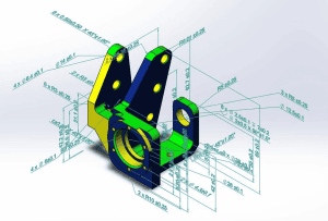
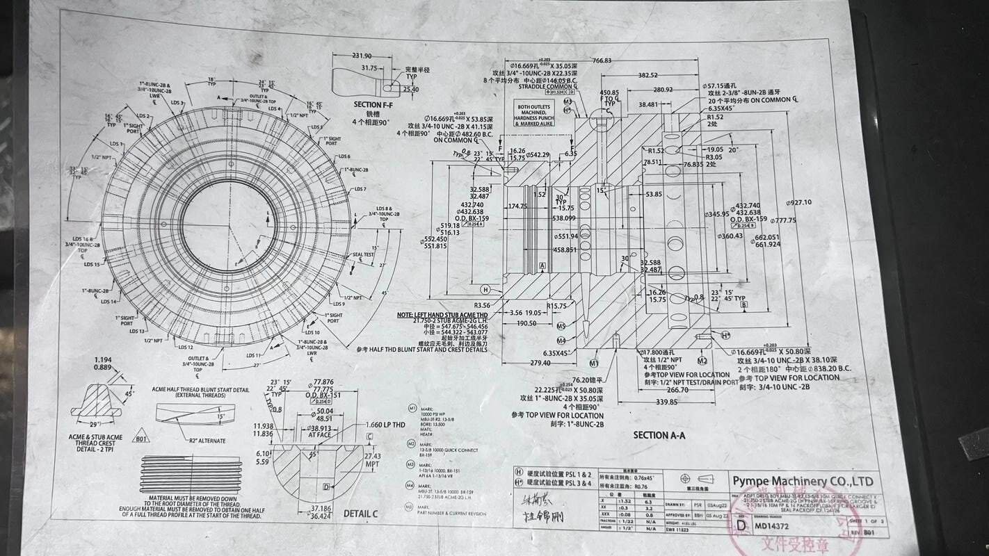

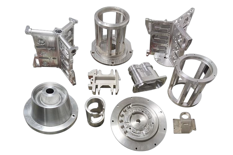
A shaft comes in 0.02 mm oversize, and suddenly the bearing press fit is wrong, assembly slows down, and your prototype schedule slips. That is why machining tolerances explained in practical terms matter far more than a drawing note. Tolerance is not just an engineering detail. It directly affects part function, inspection time, scrap risk, and the price you pay.
We see this issue often in custom CNC projects. A drawing may call for very tight limits on every feature, even when only two or three dimensions actually control fit or performance. That approach looks safe on paper, but it usually increases machining time, measurement complexity, and delivery risk without improving the product.
What machining tolerance actually means
A machining tolerance is the permitted variation from a nominal dimension. If a hole is specified as 10.00 mm ±0.05 mm, any finished size from 9.95 mm to 10.05 mm is acceptable. The nominal dimension tells the machinist the target. The tolerance tells us how much variation the design can allow and still work.
That sounds simple, but tolerance is really a functional decision. It defines how much process variation your part can absorb before it fails to assemble, leaks, vibrates, binds, or wears too quickly. Tightening a tolerance reduces the allowable variation. In return, you may gain better fit or performance, but you also increase manufacturing difficulty.
This is where many teams lose time. They treat tolerance as a default drafting exercise instead of a performance requirement. A good tolerance scheme reflects function, not caution.
Machining tolerances explained by feature type
Not every feature should be held to the same level of precision. Different dimensions carry different risk.
Linear dimensions such as lengths, widths, and step heights are often the most straightforward. Standard CNC machining can typically hold tolerances around ±0.05 mm to ±0.1 mm on many general features, depending on geometry, material, and setup. Tight limits such as ±0.01 mm or below are possible, but not across every part shape and not at the same cost structure.
Hole diameters deserve more attention because they affect fasteners, pins, bearings, and alignment. A reamed hole for a dowel pin has a very different requirement than a clearance hole for an M6 screw. One may need close size control and good roundness. The other simply needs enough space for assembly.
Geometric tolerances add another layer. Flatness, perpendicularity, concentricity, and position control where features sit in relation to one another. In many assemblies, geometric tolerance matters more than the basic size dimension. A perfectly sized hole in the wrong location still fails.
Surface finish also interacts with tolerance. A shaft can measure within size but still perform poorly if roughness is too high for a seal or bearing interface. For sliding or sealing surfaces, size and finish need to be considered together.
Why tighter tolerances increase cost and lead time
Every tighter tolerance narrows the process window. That has consequences at each production step.
Machining takes longer because we often need lighter cuts, more stable fixturing, additional tool offsets, or secondary finishing processes such as grinding or honing. Inspection also takes longer. A general caliper check may be enough for a loose feature, but a tight bore might need a bore gauge, air gauge, CMM verification, or controlled temperature inspection.
Yield risk rises too. If the allowed variation is small, more parts fall outside spec from tool wear, material movement, or thermal effects. Scrap increases. Rework increases. Capacity gets consumed by control rather than output.
Material choice changes the picture as well. Aluminum generally machines more predictably than some stainless steels or titanium alloys. Thin walls, long unsupported features, and deep pockets also make tight control harder because the part can deflect during cutting.
For buyers, this translates into three practical effects: higher unit cost, longer cycle time, and more dependence on a supplier’s inspection capability. If a project does not truly need ultra-tight limits, paying for them is rarely a good decision.
General tolerance vs critical tolerance
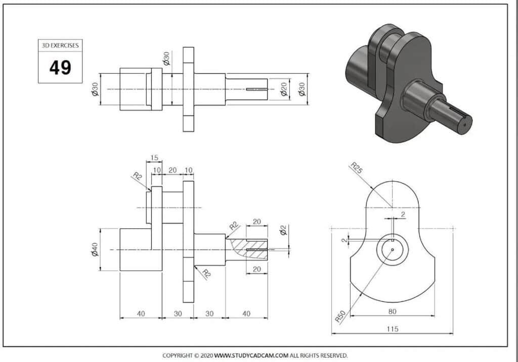
A strong drawing separates standard features from critical ones. That one decision improves manufacturability more than most teams expect.
General tolerances cover dimensions that are not especially sensitive. These are the default limits a supplier applies unless otherwise specified. Critical tolerances are placed only on features that affect fit, sealing, motion, load path, alignment, or compliance requirements.
For example, an enclosure plate may have an overall length tolerance of ±0.1 mm, but the connector opening and mounting hole pattern may need ±0.03 mm positional control. That makes sense because those features determine assembly. The outer edge often does not.
When every dimension is marked tight, nothing stands out as critical. That creates confusion during production and inspection. It also increases the chance that effort is spent controlling the wrong features.
How to choose tolerances that match function
Start with the assembly, not the isolated part. Ask which dimensions determine whether the product fits, moves, seals, locates, or meets test performance. Those are the features that deserve tighter control.
Next, consider the manufacturing process. Milling, turning, grinding, reaming, and wire EDM do not offer the same capability or economics. A tolerance that is routine in precision grinding may be expensive in standard milling. The right call depends on both the target and the process route.
Then look at stack-up. A single dimension may be forgiving on its own but risky once several mating parts accumulate variation. Critical interfaces should be reviewed as a system. This is especially relevant in fixtures, automation equipment, and electromechanical assemblies where multiple plates, pins, and shafts interact.
Inspection should also be part of the decision. If you specify a tolerance, you need a realistic way to verify it. A ±0.005 mm callout on a small internal feature means little if the inspection method is not defined or practical.
We usually recommend a simple rule: keep general dimensions as open as function allows, and tighten only the features that carry real assembly or performance risk. That shortens machining time and protects delivery without weakening quality.
Common tolerance mistakes on CNC drawings
The most common mistake is over-tolerancing. Engineers often apply precision to the whole part because they want to avoid failure. The result is usually the opposite. Quotes rise, lead times stretch, and suppliers may decline the job or add conservative pricing.
Another issue is using decimal-place conventions without functional thinking. A drawing full of three-decimal dimensions can imply a level of control that the design never actually needs. The number of digits should not replace engineering intent.
We also see incomplete callouts on hole features. A hole diameter alone is not enough when fit matters. Depth, positional accuracy, perpendicularity, and finish may all influence whether that hole works in the assembly.
The last major problem is ignoring material and geometry effects. A flatness requirement that looks reasonable on a thick steel block may become difficult on a thin aluminum plate after stress relief, anodizing, or part release from clamping.
What realistic tolerance planning looks like in production
Good tolerance planning starts before machining. We review the model, drawing, material, feature accessibility, and likely process sequence. If a part has a critical bearing seat at ±0.005 mm and the surrounding profile at ±0.1 mm, we plan those features differently. The seat may be finished in a separate pass, measured at a stable temperature, and isolated from operations that could distort it later.
This is where design for manufacturability matters. A small drawing change can reduce cost and improve stability. Moving a datum, adding relief for tool access, loosening a nonfunctional edge tolerance, or converting a blind internal corner can make a part much easier to control.
For low-volume and prototype work, this matters even more. You need speed, but you also need confidence that the first batch will assemble. A supplier with in-house machining and inspection can flag unrealistic callouts before they turn into scrap or schedule loss. At 6 CNC, that review step is often where cost and risk are reduced the fastest.
Machining tolerances explained for buyers
If you manage sourcing rather than design, tolerance still deserves close attention. Tight tolerances affect more than the quoted price. They influence supplier selection, inspection documents, acceptance criteria, and the chance of production delay.
When evaluating a quote, ask which dimensions are truly driving cost. A good manufacturing partner should be able to tell you whether the issue is a bore size, a positional tolerance, a flatness callout, or a finishing requirement. That level of feedback helps you decide whether the tolerance is worth keeping.
You should also verify how the part will be measured. For high-precision custom parts, inspection capability is not a side issue. It is part of the manufacturing capability. A supplier who can machine to a limit but cannot reliably verify it leaves you exposed.
The best tolerance strategy is not the tightest one. It is the one that gives your part the precision it needs, without adding avoidable cost or schedule risk. If you treat tolerance as a functional tool instead of a blanket requirement, you usually get better parts and a smoother project.